
Isolating active electron spin signals in epr

Active Publication Date: 2014-01-09
PEPRIC
View PDF3 Cites 9 Cited by
  • Summary
  • Abstract
  • Description
  • Claims
  • Application Information

AI Technical Summary

Benefits of technology

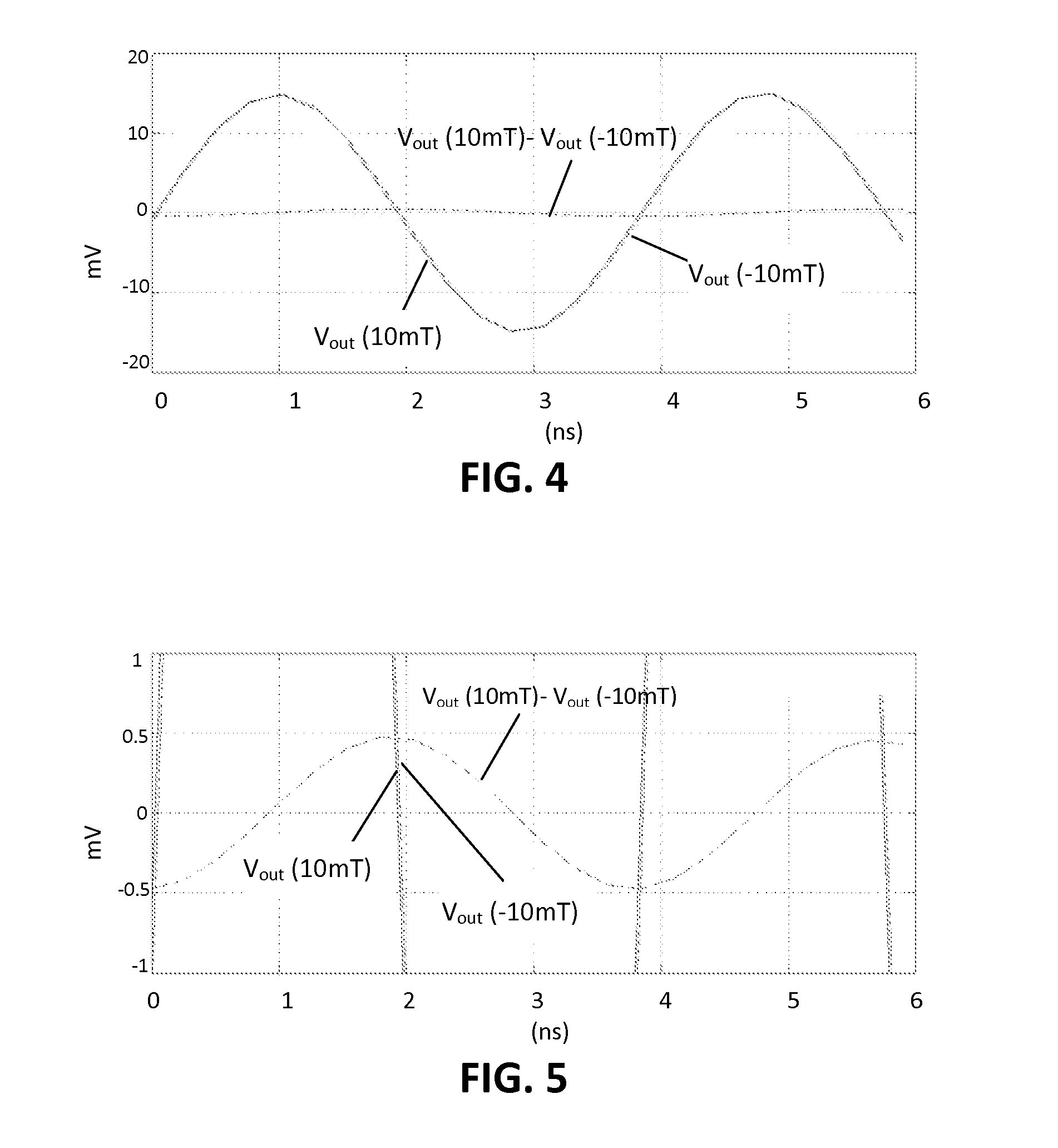
The present invention allows for the isolation of the signals from electrons spins of para magnetic particles in an R&D setting. This is helpful in removing common mode signals that may interfere with the measurements. Combining the signals can be done by measuring them in time intervals when the amplitude of one of the signals is below a certain level. This improves the amplification beyond the detection unit's dynamic range.

Problems solved by technology

CW-EPR may require longer acquisition times and may hence be more susceptible to motion artifacts.
Imaging techniques based on CW-EPR offer relatively low resolution and low sensitivity and can exhibit diverse artifacts related to magnetic field modulation, power saturation and motion.
These requirements are mutually conflicting, and limit the suitability of pulsed EPR to signals emitted by paramagnetic particles with narrow linewidths, and therefore long relaxation times, since broad linewidth particles would require an extremely short resonator recovery time.

Method used


Image

  • Isolating active electron spin signals in epr
  • Isolating active electron spin signals in epr
  • Isolating active electron spin signals in epr

Examples


Embodiment Construction

[0054]The present invention will be described with respect to particular embodiments and with reference to certain drawings but the invention is not limited thereto but only by the claims. The drawings described are only schematic and are non-limiting. In the drawings, the size of some of the elements may be exaggerated and not drawn on scale for illustrative purposes. The dimensions and the relative dimensions do not correspond to actual reductions to practice of the invention.

[0055]Furthermore, the terms first, second and the like in the description and in the claims, are used for distinguishing between similar elements and not necessarily for describing a sequence, either temporally, spatially, in ranking or in any other manner. It is to be understood that the terms so used are interchangeable under appropriate circumstances and that the embodiments of the invention described herein are capable of operation in other sequences than described or illustrated herein.

[0056]Moreover, t...


PUM


Abstract

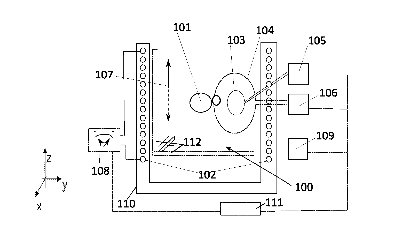
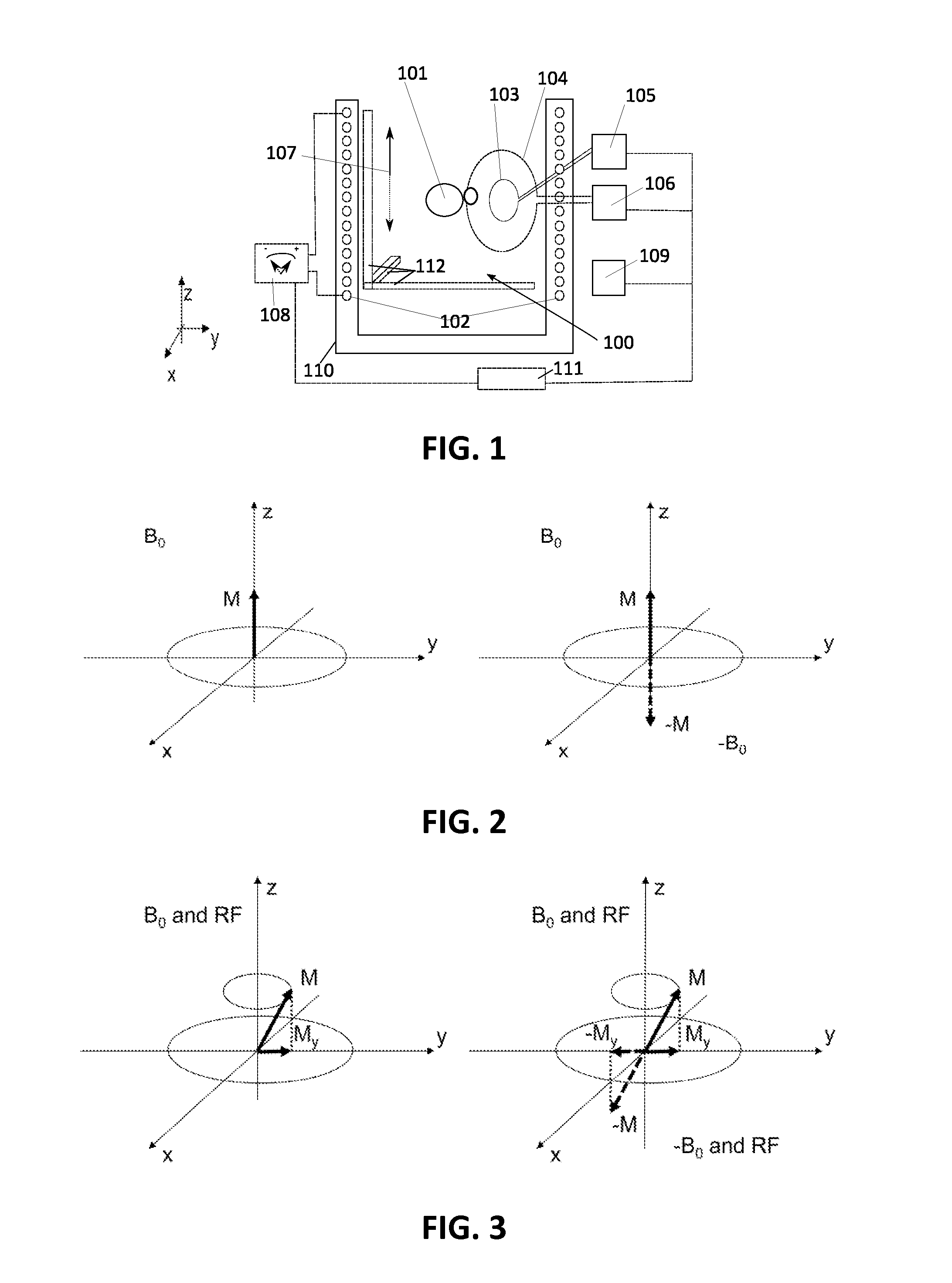
A system and method involve performing electron paramagnetic resonance on an object under study. The system comprises a first field generator adapted for generating an orienting magnetic field for orienting the magnetization of the object under study and a second field generator adapted for generating RF excitation waves at a frequency to generate electron paramagnetic resonance (EPR) in the object under test. The system also comprises a detection unit adapted for detecting the EPR signals emitted by the object under test and a control unit adapted for controlling the relative orientation of the orienting magnetic field induced by the first field generator with respect to the detection unit. The system furthermore comprises a processing unit programmed for combining detected EPR signals obtained using different relative orientations of the orienting magnetic field with respect to the detection unit.

Description

FIELD OF THE INVENTION[0001]The invention relates to the field of electron paramagnetic resonance. More specifically the present invention relates to methods and systems for electron paramagnetic resonance spectroscopy and imaging based thereon.BACKGROUND OF THE INVENTION[0002]Electron paramagnetic resonance (EPR) allows spectroscopic analysis of substances based on physical concepts analogous to those used in nuclear magnetic resonance (NMR). While NMR allows analysis of substances containing nuclides with non-zero spin, EPR is only applicable to substances containing chemical agents that possess at least one unpaired electron. NMR proves particularly useful in the analysis of substances comprising hydrogen atoms, which are abundantly present in water and hydrocarbons. Furthermore, Magnetic Resonance Imaging (MRI), an imaging technique based on NMR, is a valuable tool in medical diagnosis, due to the subtle contrasts caused by water density and complex spin-spin and spin-lattice in...

Claims


Application Information

Patent Timeline
IPC IPC(8): G01R33/60
CPCG01R33/60G01N24/10
Inventor VAES, PETERTEUGHELS, STEPHANIE
Owner PEPRIC
Learn More