Organic Compound, Light-Emitting Element, Light-Emitting Device, Electronic Device, and Lighting Device
a technology of light-emitting elements and organic compounds, which is applied in the direction of organic chemistry, solid-state devices, thermoelectric devices, etc., can solve the problems of difficult synthesizing and practical use, and achieve the improvement of emission efficiency, emission characteristics, and reliability of light-emitting elements.
- Summary
- Abstract
- Description
- Claims
- Application Information
AI Technical Summary
Benefits of technology
Problems solved by technology
Method used
Image
Examples
embodiment 1
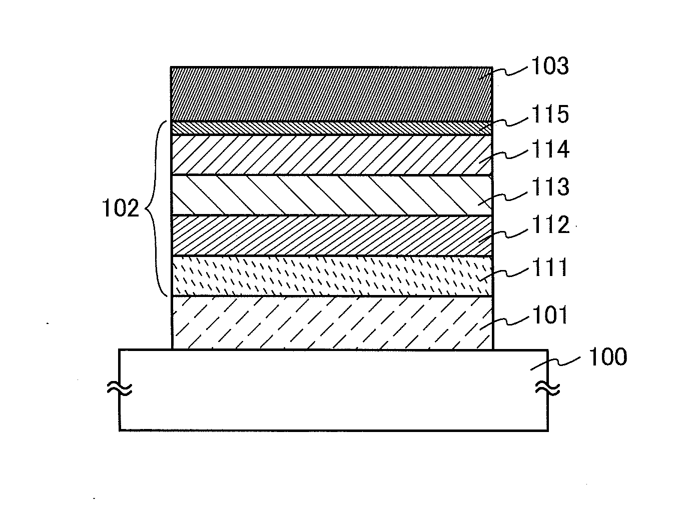
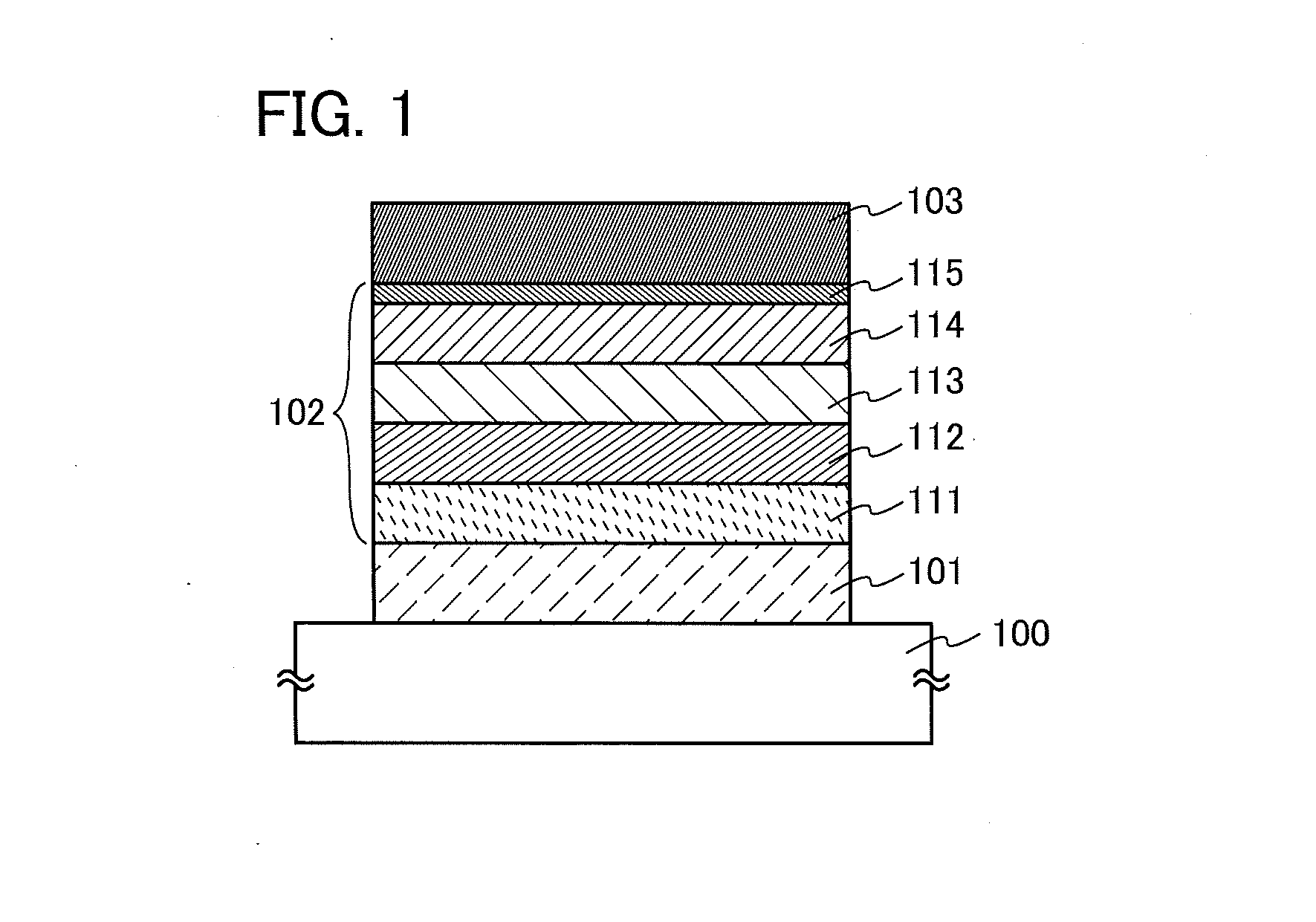
[0061]In this embodiment, a light-emitting element which includes a light-emitting layer between a cathode and an anode will be described with reference to FIG. 1.
[0062]As illustrated in FIG. 1, the light-emitting element in this embodiment includes an EL layer 102 between a first electrode 101 and a second electrode 103. The EL layer 102 includes at least a light-emitting layer 113 and also includes a hole-injection layer 111, a hole-transport layer 112, an electron-transport layer 114, an electron-injection layer 115, and the like. Note that in this embodiment, the first electrode 101 is used as an anode and the second electrode 103 is used as a cathode.
[0063]The light-emitting layer 113 contains an organic compound in which an imidazo[1,2-f]phenanthridine skeleton and a dibenzothiophene skeleton or a dibenzofuran skeleton are bonded through an arylene group.
[0064]The imidazo[1,2-f]phenanthridine skeleton with an electron-transport property and the dibenzothiophene skeleton or dib...
embodiment 2
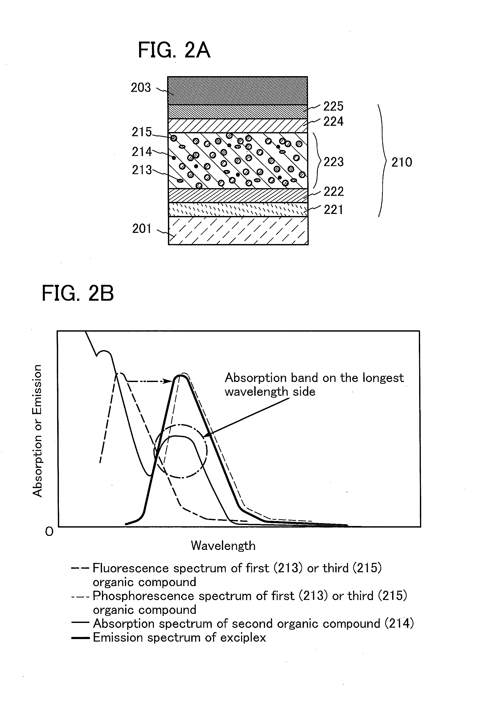
[0113]In this embodiment, a light-emitting element in which the organic compound of one embodiment of the present invention, a light-emitting material which converts triplet excitation energy into light, and a hole-transport material are used for a light-emitting layer will be described with reference to FIGS. 2A and 2B.
[0114]A light-emitting element described in this embodiment includes an EL layer 210 between a first electrode 201 and a second electrode 203 as illustrated in FIG. 2A. Note that the EL layer 210 includes at least a light-emitting layer 223 and may further include a hole-injection layer 221, a hole-transport layer 222, an electron-transport layer 224, an electron-injection layer 225, and the like. The materials in Embodiment 1 which can be used for the hole-injection layer 111, the hole-transport layer 112, the electron-transport layer 114, and the electron-injection layer 115 can be respectively used for the hole-injection layer 221, the hole-transport layer 222, th...
embodiment 3
[0127]In this embodiment, as one embodiment of the present invention, a light-emitting element (hereinafter referred to as tandem light-emitting element) in which a charge-generation layer is provided between a plurality of EL layers will be described.
[0128]A light-emitting element described in this embodiment is a tandem light-emitting element including a plurality of EL layers (a first EL layer 311 and a second EL layer 312) between a first electrode 301 and a second electrode 303, as illustrated in FIG. 3A.
[0129]In this embodiment, the first electrode 301 functions as an anode, and the second electrode 303 functions as a cathode. Note that the first electrode 301 and the second electrode 303 can have structures similar to those described in Embodiment 2. Although the plurality of EL layers may have the structures similar to those described in Embodiment 1 or 2, any of the EL layers may have a structure similar to that described in Embodiment 1 or 2. In other words, the structures...
PUM
 Abstract
Description
Claims
Application Information
 - R&D
- Intellectual Property
- Life Sciences
- Materials
- Tech Scout
- Unparalleled Data Quality
- Higher Quality Content
- 60% Fewer Hallucinations
Browse by: Latest US Patents, China's latest patents, Technical Efficacy Thesaurus, Application Domain, Technology Topic, Popular Technical Reports.
© 2025 PatSnap. All rights reserved.Legal|Privacy policy|Modern Slavery Act Transparency Statement|Sitemap|About US| Contact US: help@patsnap.com


