Biosensor array formed by junctions of functionalized electrodes

Active Publication Date: 2014-01-16
LEXOGEN GMBH
View PDF4 Cites 23 Cited by
  • Summary
  • Abstract
  • Description
  • Claims
  • Application Information

AI Technical Summary

Benefits of technology

[0038]Furthermore, the explicit disclosure of WO 2010/1204479 does not allow the fabrication of two-dimensional sensor arrays. The row element shown in black is functionalized with polyT-oligonucleotides homooligomer material that nonspecifically binds to all m RNA target molecules. Only the functionalizing sensor compounds at the column-elements, shown in white, binds specifically to certain target molecules. In the disclosure of WO 2010/1204479 sensor compounds with 21 nucleotides are used, which is highly specific and emphasizes the matter, that the sensor compound shall only be used for one distinct single sensor which targets one specific compound.
[0039]The disclosure of WO 2010/1204479 does even dissuade the person skilled in the art from reusing the same sensor compound for different sensors. The first compound, the polyT-oligonucleotide homooligomer annealing probe that is used for the row elements is nonspecific. Multiple uses would not lead to more different specific sensors. The second compound comprising a sequence of 21 nucle

Problems solved by technology

At tiny submicrometer dimensions the challenges lie in, firstly, aligning electrodes as narrowly as possible but preventing short circuits, secondly,

Method used


Image

  • Biosensor array formed by junctions of functionalized electrodes
  • Biosensor array formed by junctions of functionalized electrodes
  • Biosensor array formed by junctions of functionalized electrodes

Examples


first preferred embodiment

Woven Network of Conductors—from the Array Assembly to the Measurement

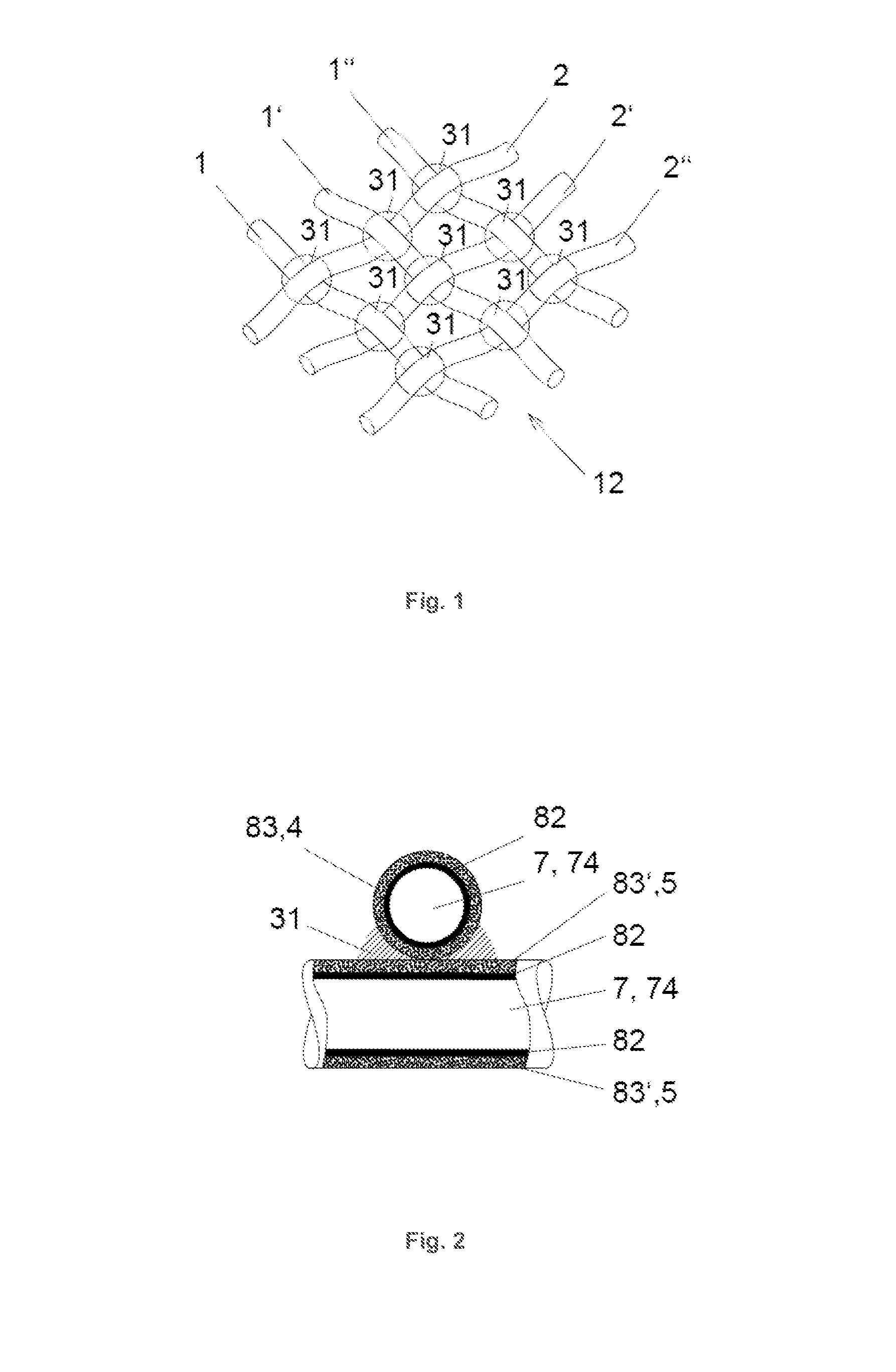
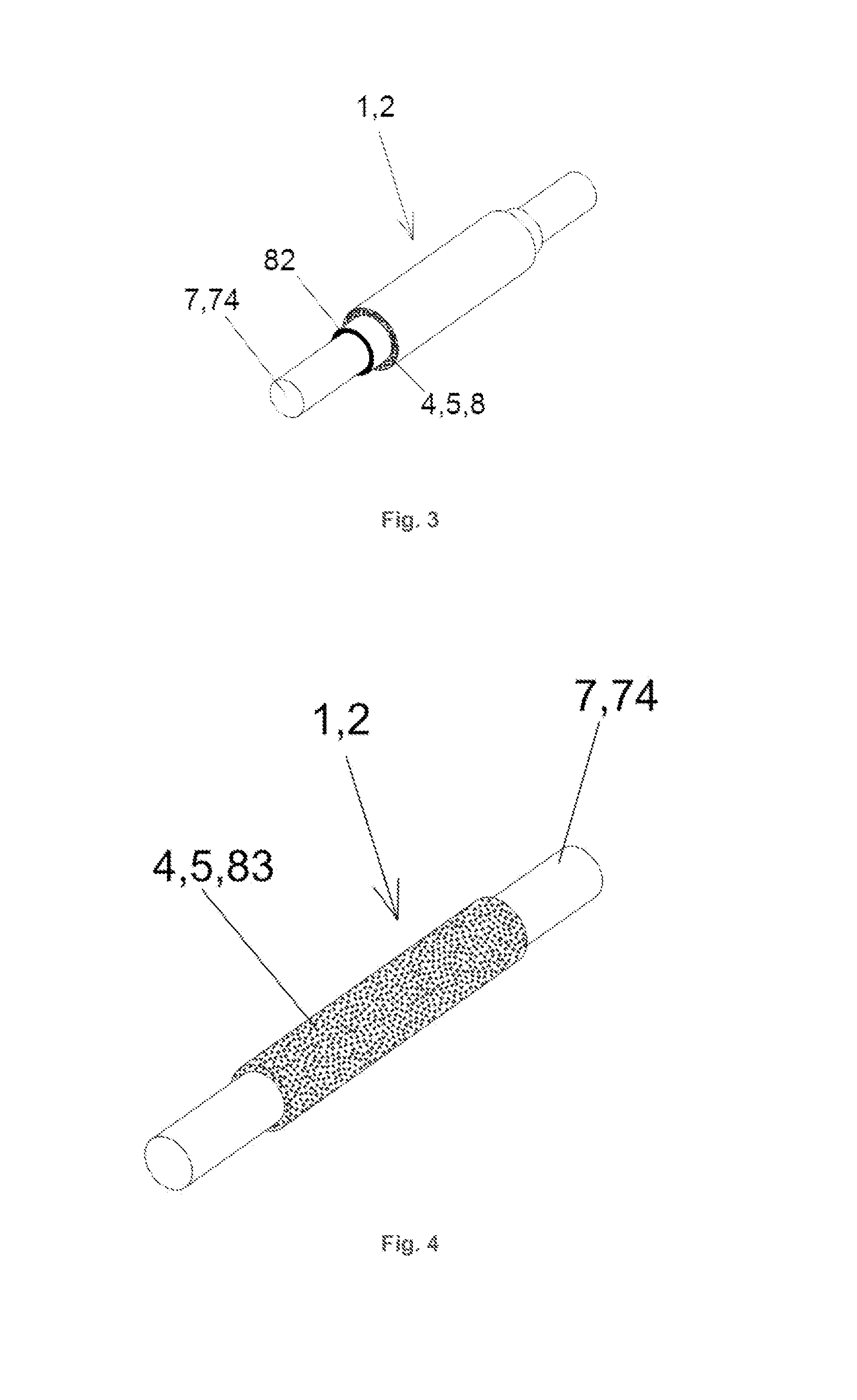
[0123]The first preferred embodiment of the invention, which is shown in FIG. 1, describes a sensor array 12 with woven sensor half elements 1, 2, which are grouped as row elements 1 and column elements 2. One group of unidirectional sensor half elements 1, 2 is denoted as row elements 1. The remaining sensor half elements 1, 2 are referred to as column elements 2. Together, the sensor half elements 1, 2 are assembled in a weave-like or woven structure. Accordingly, each row element 1 intersects or crosses or approaches or touches each column element 2 in exactly one junction area 31. The number of junction areas 31 within one sensor array 12 equals to the product of the number of row elements 1 and column elements 2.

[0124]The present example contains linear sensor half elements 1, 2 as shown in FIG. 2. The carrier 7 is an elongated conductor 74 and has a convex almost circular cross-section. The cross section of ...

second preferred embodiment

Sensor Arrays with Common Carrier Plates

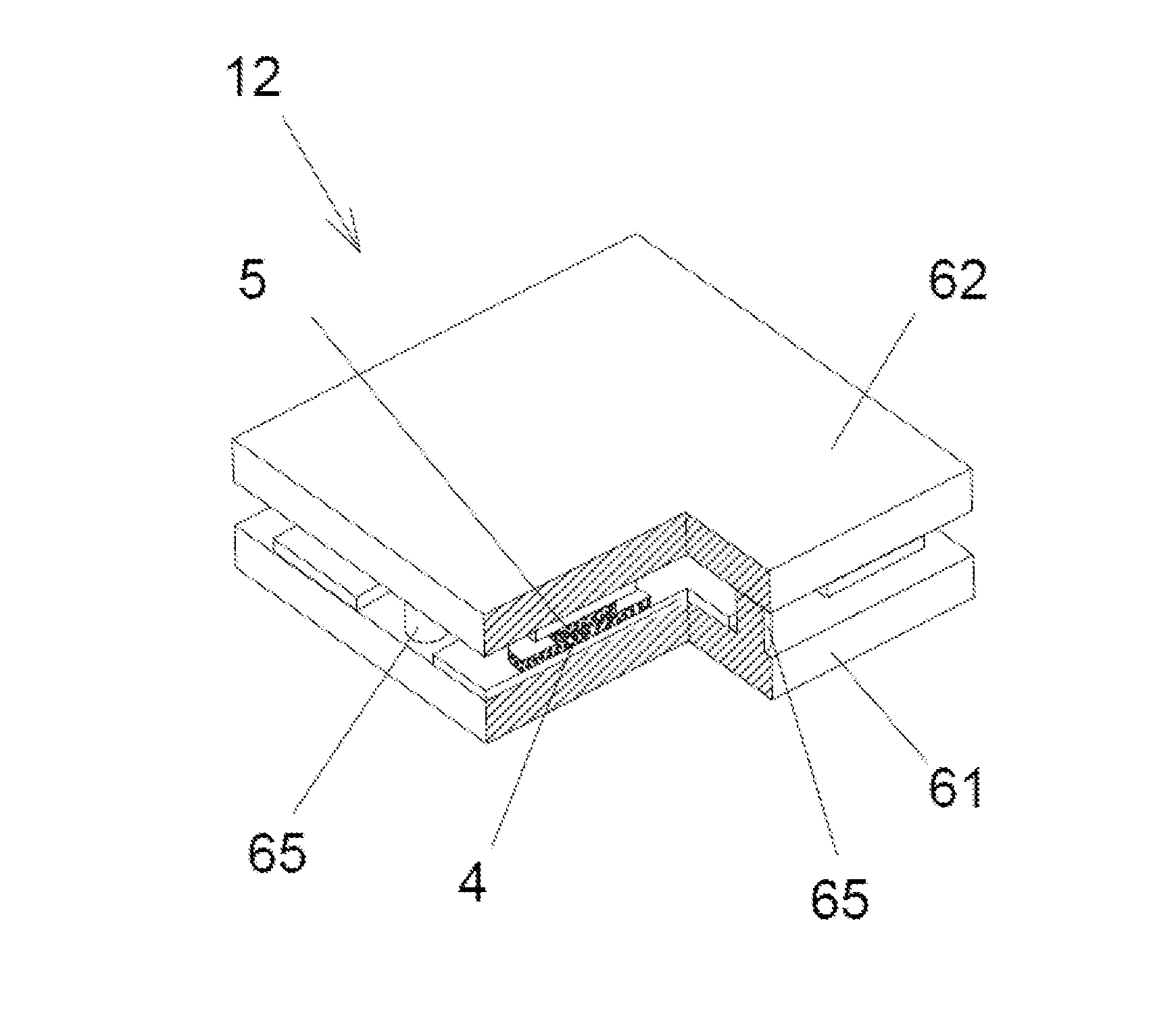
[0206]The second preferred embodiment describes structures which are fabricated through arranging and aligning sensor half elements 1, 2 on one of two common carriers 61, 62 as shown in FIG. 14.

[0207]The sensor half elements 1, 2 are functionalized according to the method of functionalization as described above. Each of the row elements 1 is arranged and aligned on the first common carrier 61, each of the column elements 2 is arranged and aligned on the second common carrier. The sensor half elements 1, 2 are supported by the respective common carrier 61, 62. In this preferred embodiment of the invention, the row elements 1 are arranged in parallel on the first common carrier 61 and the column elements 2 are arranged in parallel on the second common carrier 62. One of the common carriers 61, 62 is depicted in FIG. 15. The row elements 1 and the column elements 2 are aligned perpendicular to each other. The parts of the surface of the row eleme...


PUM

PropertyMeasurementUnit
Shapeaaaaaaaaaa
Areaaaaaaaaaaa
Capacitanceaaaaaaaaaa

Abstract

We provide a sensor array device for the measurement of mixtures of organic compounds comprising an assembly of sensor half elements which have been functionalized through sensor compounds before the assembly. Each individual sensor of the array contains two sensor compounds pounds which are bound at opposite sensor half elements. The molecular recognition is bi-functional. While the amount of sensor compounds increases linearly, the individual sensors increase with the second power.

Description

[0001]We provide a sensor array device for the measurement of mixtures of organic compounds comprising an assembly of sensor half elements which have been functionalized through sensor compounds before the assembly. Each individual sensor of the array contains two sensor compounds which are bound at opposite sensor half elements. The molecular recognition is bi-functional. While the amount of sensor compounds increases linearly, the individual sensors increase with the second power.FIELD OF INVENTION[0002]The invention relates to a sensor array as disclosed in claim 1. Embodiments of the invention relate to the field of biosensor arrays for the detection and characterization of mixtures of different organic compounds, in particular RNA's, DNA's or proteins. Beside their use in the biological, pharmaceutical and medical research such kind of sensor arrays can also be applied in diagnostics. One example is the characterization of gene expression patterns, transcriptomes. Here, the kin...

Claims


Application Information

Patent Timeline
IPC IPC(8): C12Q1/68
CPCC12Q1/6837G01N27/3278G01N33/553G01N33/5438B82Y15/00
Inventor REDA, TORSTENHOLLANDER, IGORSEITZ, ALEXANDER
Owner LEXOGEN GMBH
Why Eureka
Try Eureka