
Method And Apparatus for Stabilization of Optical Transmitter

a technology of optical transmitter and optical fiber, which is applied in the direction of electrical equipment, electromagnetic transmission, multiplex communication, etc., can solve the problems of high bit-rate data transmission through optical fiber, high optical fiber nonlinearity of high-bit-rate systems, and difficult electronic data processing

Active Publication Date: 2014-01-23
II VI DELAWARE INC
View PDF8 Cites 53 Cited by
  • Summary
  • Abstract
  • Description
  • Claims
  • Application Information

AI Technical Summary

Benefits of technology

The patent describes a new technology called Dual Polarization QPSK (DP-QPSK) which reduces the data rate of a communication system by transmitting four bits per optical symbol. This technology uses coherent detection and compensates for distortion and error introduced by the transmission process. By using this technology, the system can achieve a bit rate that is four times higher than its baud rate, which means that fewer symbols need to be transmitted per second. This reduces the amount of optical bandwidth required, allowing more optical channels in the same spectral band. The information can then be processed by commonly available digital signal processing (DSP) hardware and software which significantly reduce the requirements of the optical interworking hardware. Overall, this technology provides a way to achieve high-speed data transmission with reduced bandwidth requirements and improved signal quality.

Problems solved by technology

The increasing need for high bit-rate data transmissions through optical fibers presents significant challenges to the fiber-optic telecommunications industry.
For example, high bit-rate systems are highly susceptible to optical fiber nonlinearities.
In addition, the high bit-rate systems make electronic processing of data very difficult.

Method used


Image

  • Method And Apparatus for Stabilization of Optical Transmitter
  • Method And Apparatus for Stabilization of Optical Transmitter
  • Method And Apparatus for Stabilization of Optical Transmitter

Examples


Embodiment Construction

[0014]Reference in the specification to “one embodiment” or “an embodiment” means that a particular feature, structure, or characteristic described in connection with the embodiment is included in at least one embodiment of the teaching. The appearances of the phrase “in one embodiment” in various places in the specification are not necessarily all referring to the same embodiment.

[0015]It should be understood that the individual steps of the methods of the present teachings may be performed in any order and / or simultaneously as long as the teaching remains operable. Furthermore, it should be understood that the apparatus and methods of the present teachings can include any number or all of the described embodiments as long as the teaching remains operable.

[0016]The present teaching will now be described in more detail with reference to exemplary embodiments thereof as shown in the accompanying drawings. While the present teachings are described in conjunction with various embodimen...


PUM


Abstract

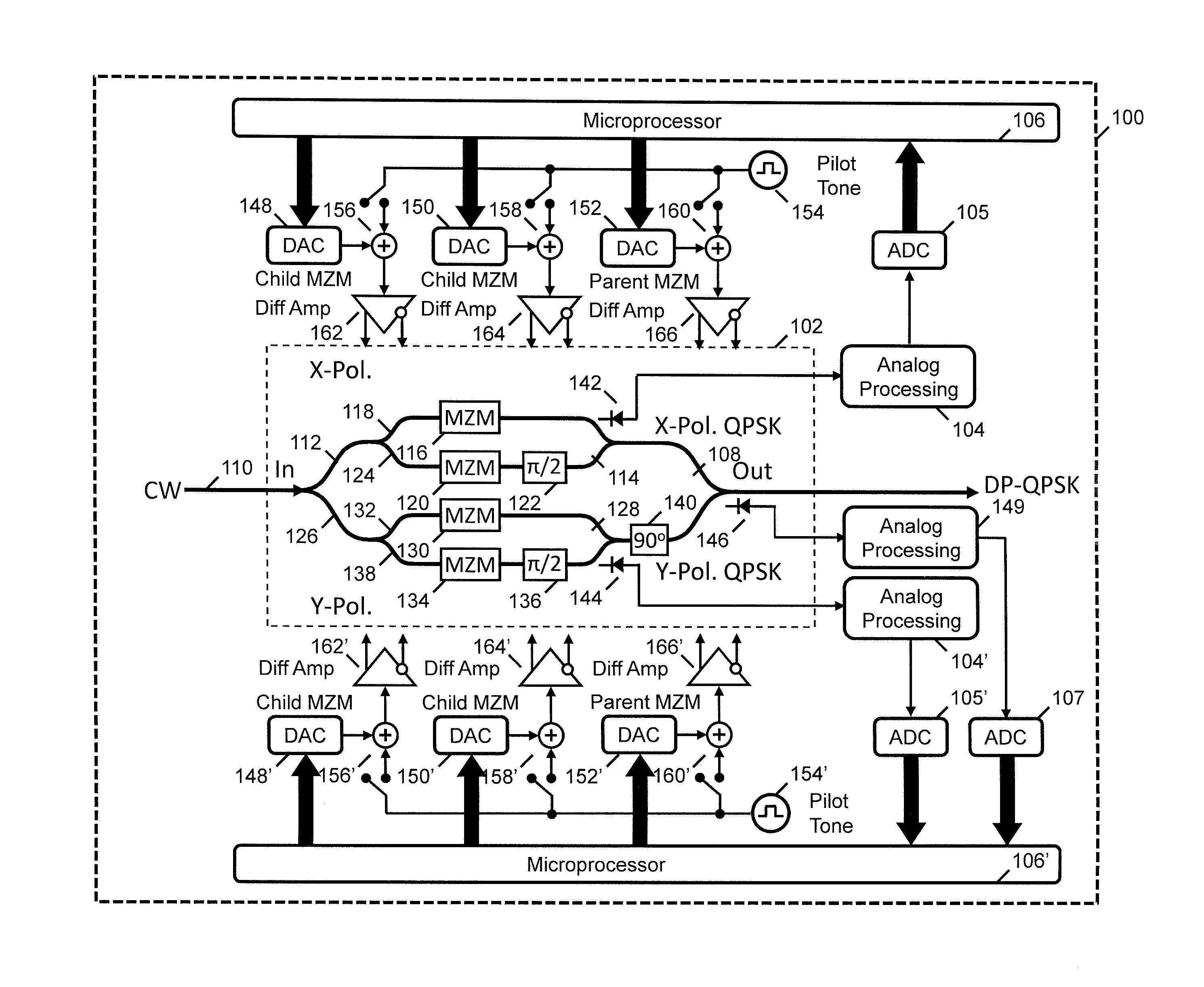
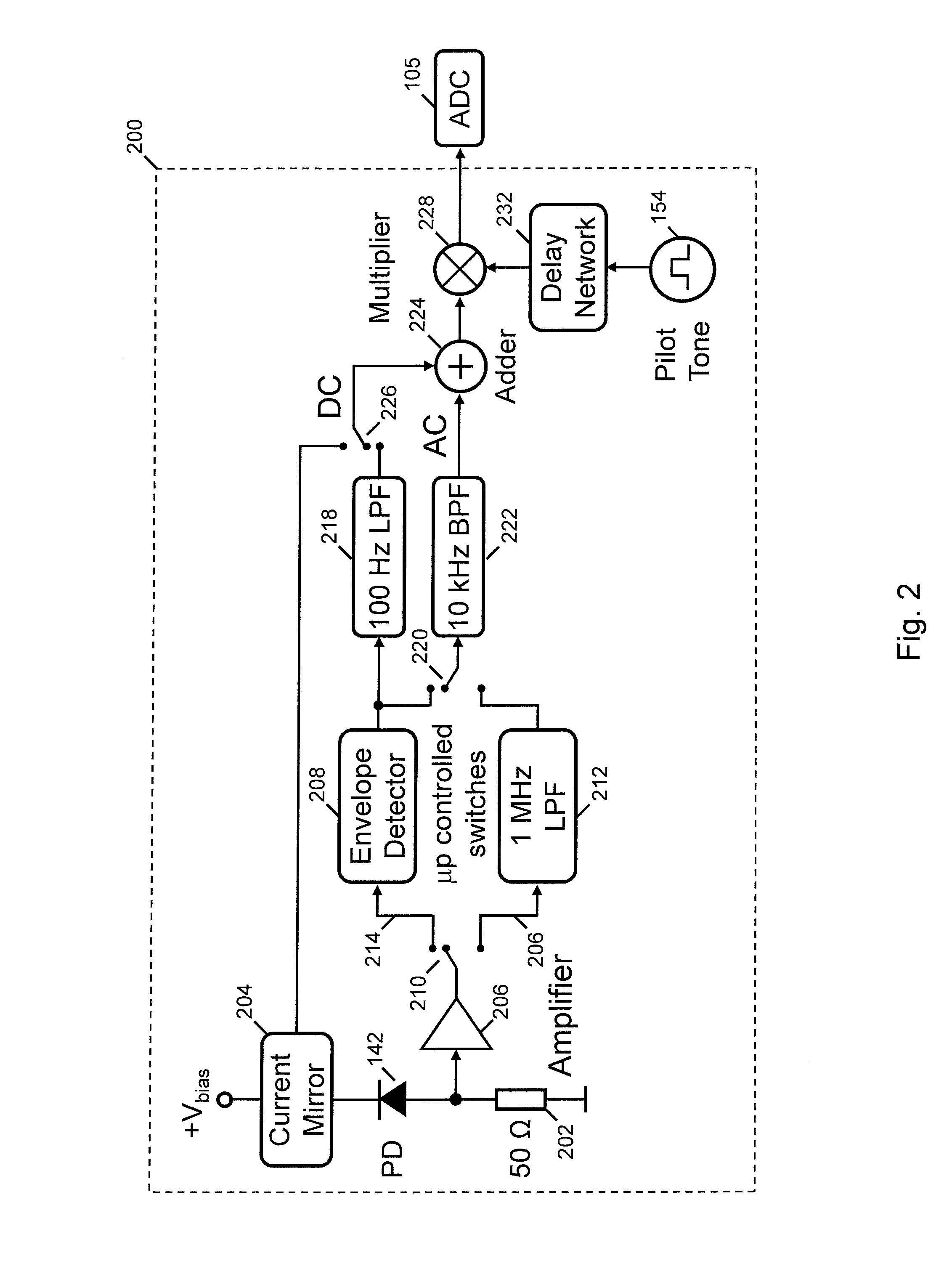
A DP-QPSK optical transmitter includes an outer MZM comprising a first parent MZM comprising a first child MZM and a second child MZM that modulates a QPSK signal with a first polarization. A second parent MZM includes a first child MZM and a second child MZM that modulates a QPSK signal with a second polarization. The outer Mach-Zehnder modulator multiplexes the first and second polarization embedded into a dual-polarization QPSK signal generation. A first optical detector detects the QPSK signal generated by the first parent MZM with the first polarization. A second optical detector optical detects the QPSK signal generated by the second parent Mach-Zehnder modulator with the second polarization. A bias control circuit generates bias signals on at least one output that stabilize the DP-QPSK signal in response to signals generated by the first and second optical detector using electrical time division multiplexing.

Description

INTRODUCTION[0001]The increasing need for high bit-rate data transmissions through optical fibers presents significant challenges to the fiber-optic telecommunications industry. For example, high bit-rate systems are highly susceptible to optical fiber nonlinearities. In addition, the high bit-rate systems make electronic processing of data very difficult.[0002]One option to confront these challenges is to transmit the data in a Dual-Polarization Quadrature Phase-Shift Keying (DP-QPSK) format. Quadrature phase shift keying involves representing the data in the complex plane, so that each symbol consists of a real (in-phase) and an imaginary (quadrature phase) part. In the DP-QPSK modulation format, independent data transmissions take place on two orthogonal polarizations. One signal is transmitted in the horizontal polarization and the other signal is transmitted in the vertical polarization. However, both signals have the same optical frequency, and they are polarized 90° with resp...

Claims


Application Information

Patent Timeline
Patent Type & Authority Applications(United States)
IPC IPC(8): H04B10/04H04J14/00
CPCH04B10/532H04B10/5053H04B10/50575H04B10/5561H04J14/06
Inventor BHANDARE, SUHAS P.EREIFEJ, HEIDERKIM, KYUCOLYAR, MARK
Owner II VI DELAWARE INC
Learn More