Eureka AIR delivers breakthrough ideas for toughest innovation challenges, trusted by R&D personnel around the world.

Methods, apparatuses and systems for collection of tissue sections

a tissue section and collection method technology, applied in the field of tissue section collection methods, apparatuses and systems, can solve the problems of inability to address the needs of the larger community of neuroscientists, the current approach of attempting to integrate thousands of individual in vivo tracing experiments into a coherent whole, and the inability to achieve the goal of achieving the goal of reducing the number of tissue sections collected, and reducing the risk of tissue damag

Active Publication Date: 2014-01-30
PRESIDENT & FELLOWS OF HARVARD COLLEGE
View PDF2 Cites 43 Cited by
  • Summary
  • Abstract
  • Description
  • Claims
  • Application Information

AI Technical Summary

Benefits of technology

The patent suggests using automation to collect tissue samples, which could help reduce damage to the samples and make it easier to image them. This would help improve the mapping of larger tissue structures.

Problems solved by technology

Such experiments and models involve brain systems where incomplete information regarding the system's underlying neural circuitry presents one of the largest barriers to research success.
The current approach of attempting to integrate thousands of individual in vivo tracing experiments into a coherent whole has been considered to be a virtually impossible task.
Because of the manual nature of this current process, this technique is impractical to apply to larger brain structures and so it is currently unable to address the needs of the larger community of neuroscientists who require a map of the brain connectivity of rodent and primate brains.
Extending these manual tissue imaging technologies to map structures that are 1×10⁵ (mouse brain) and 1×10⁸ (human brain) times as large as C Elegans presents a significant challenge.
However, these designs are targeted toward automating the slicing process only, and do not address the tissue collection and handling processes.
Thus, current conventional “automated microtome” designs still require manual slice retrieval and manual slide or grid mounting for imaging.
A tissue sample sectioned by an ultramicrotome typically results in fragile strips of tissue that come off the ultramicrotome knife and float on a surface of water contained within a knife boat of the ultramicrotome.
The fragile strips of tissue are manually collected onto slot grids for use in transmission electron microscopy (TEM) by employing a highly unreliable and painstaking positioning process.
Such manual slice retrieval necessitates that skilled, delicate, and incredibly time-consuming work be expended on each tissue slice (or small series of slices) as it involves “fishing” each tissue slice out of a water boat attached to the knife of the conventional ultramicrotome instrument and onto a TEM grid.
Such a collection process drastically limits the total volume of tissue that can be sectioned and imaged.
In addition, no matter how experienced and skilled the technician may be at moving tissue strips to the slot grids, manual intervention will inevitably result in damage to at least some of the collected tissue sections.
Further, the manual nature of the collecting process also requires continual starting and stopping of the ultramicrotome to allow for the tissue sections to be manually collected, adversely impacting the precision of the cutting process.
To compensate for such disturbances, tissue sections are typically cut thicker, thus, limiting the overall resolution of electron microscopy imaging to be performed on the tissue.

Method used


Image

  • Methods, apparatuses and systems for collection of tissue sections
  • Methods, apparatuses and systems for collection of tissue sections
  • Methods, apparatuses and systems for collection of tissue sections

Examples


Embodiment Construction

[0068]It should be understood that aspects of the invention are described herein with reference to the figures, which show illustrative embodiments in accordance with aspects of the invention. The illustrative embodiments described herein are not necessarily intended to show all aspects of the invention, but rather are used to describe a few illustrative embodiments. Thus, aspects of the invention are not intended to be construed narrowly in view of the illustrative embodiments. It should be appreciated, then, that the various concepts and embodiments introduced above and those discussed in greater detail below may be implemented in any of numerous ways, as the disclosed concepts and embodiments are not limited to any particular manner of implementation. In addition, it should be understood that aspects of the invention may be used alone or in any suitable combination with other aspects of the invention.

I. Overview

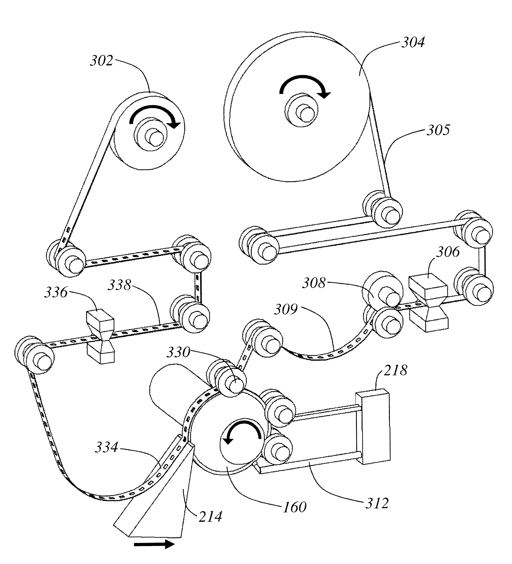
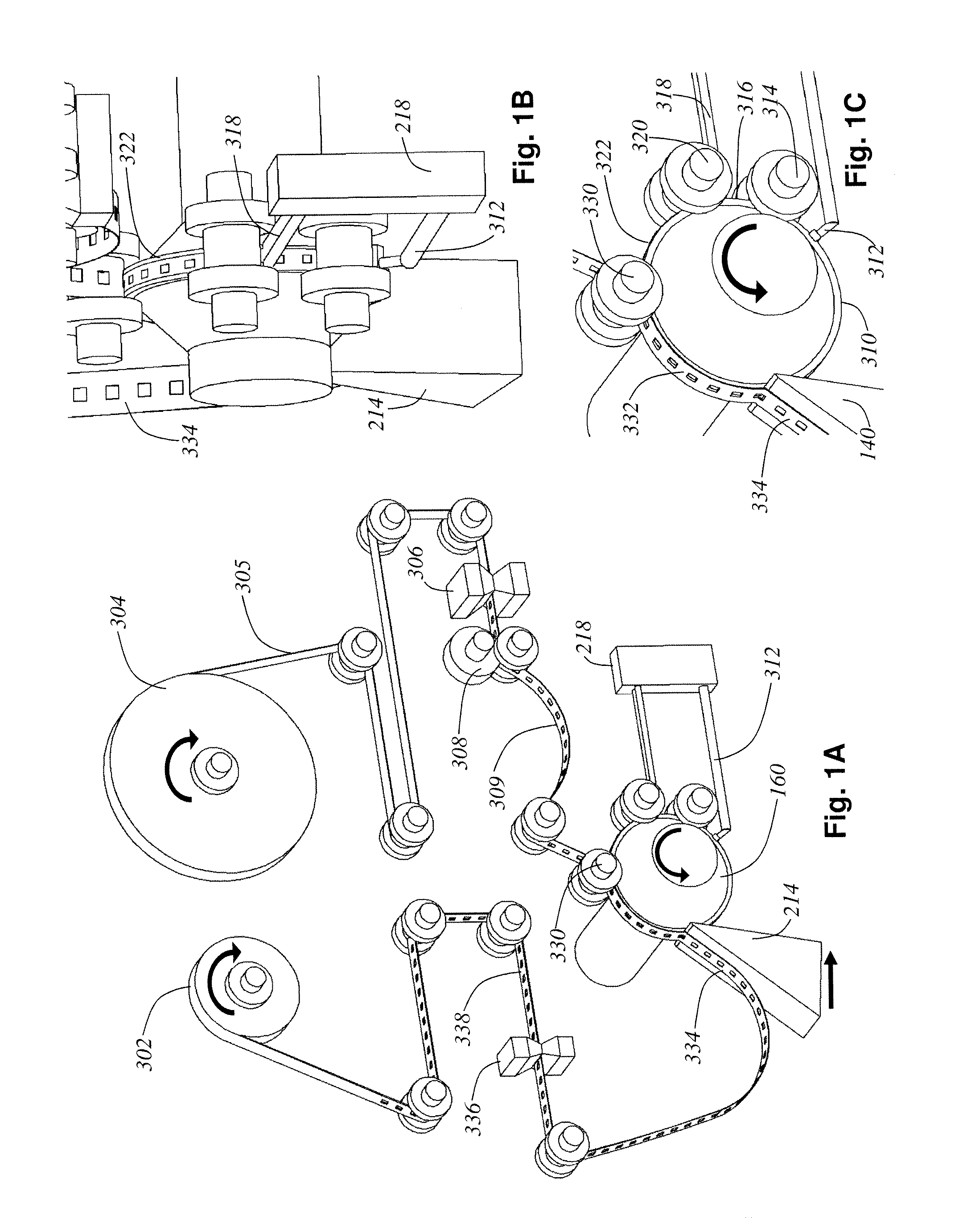
[0069]Various embodiments disclosed herein relate generally to automa...


PUM


Abstract

Methods, apparatuses and systems for facilitating automated or semi-automated collection of tissue samples cut by a microtome. In one example, a collection apparatus may be moved back and forth between respective positions at which the collection apparatus is operatively coupled to a microtome so as to collect cut tissue samples, or routine access to the microtome is provided. Relatively easy movement and positioning of the collection apparatus is facilitated, while at the same time ensuring structural stability and appropriate alignment and / or isolation between the collection apparatus and the microtome. A fluid reservoir receives samples cut by the microtome, and the collection apparatus may collect samples via a conveyor-like substrate disposed near / in the reservoir. A linear movement of the substrate may be controlled based on a cutting rate of the microtome, and the fluid level in the reservoir may be automatically maintained to facilitate effective sample collection.

Description

RELATED APPLICATIONS[0001]This application claims priority to U.S. Provisional Application No. 61 / 393,185 filed Oct. 14, 2010, entitled “Methods, Apparatuses and Systems for Collection of Tissue Sections.” This application also claims priority to U.S. Provisional Application No. 61 / 380,484 filed Sep. 7, 2010, entitled “Automatic Tape-Collection Mechanism for Ultramicrotomes.”DESCRIPTION OF RELATED ART[0002]Today neuroscientists are routinely carrying out increasingly advanced physiological experiments and cognitive scientists are proposing and testing increasingly comprehensive models of brain function. Such experiments and models involve brain systems where incomplete information regarding the system's underlying neural circuitry presents one of the largest barriers to research success. It is widely accepted within the neuroscience community that what is needed is a comprehensive and reliable wiring diagram of the brain that will provide a neuroanatomical scaffolding (and a set of ...

Claims


Application Information

Patent Timeline
IPC IPC(8): A61B16/00
CPCA61B16/00G01N35/00009G01N1/06G01N2001/065G01N2001/066G01N2001/061G01N2001/068
Inventor HAYWORTH, KENNETH JEFFREYSCHALEK, RICHARDTAPIA, JUAN CARLOSKASTHURI, NARAYANANLICHTMAN, JEFF
Owner PRESIDENT & FELLOWS OF HARVARD COLLEGE
Why Eureka
Eureka Blog
Learn More