Consumable electrode arc welding method

a technology of electrode arc welding and consumable electrode, which is applied in the direction of welding apparatus, electric heating, manufacturing tools, etc., can solve the problems of unstable welding state, difficulty in keeping the chip-base distance constant, and hindering proper welding, so as to prevent the adverse effect of improper operation of constriction detection control

Active Publication Date: 2014-01-30
DAIHEN CORP
View PDF3 Cites 1 Cited by
  • Summary
  • Abstract
  • Description
  • Claims
  • Application Information

AI Technical Summary

Benefits of technology

[0010]According to the present invention, in performing welding while executing both of constriction detection control and feed rate variable control, the transient response time of feed rate variable control is set long (high speed transient response) at the start of the welding. When erroneous constriction detection occurs at a frequency higher than a predetermined frequency during the welding, the transient response time of feed rate variable control is set long (low speed transient response), thereby preventing adverse effect by improper operation of constriction detection control. According to this arrangement, when improper operation of constriction detection control does not occur, the transient response of feed rate variable control is at high speed. Thus, the effect of constriction detection control and feed rate variable control are achieved as much as possible. When improper operation of constriction detection control occurs, the transient response of feed rate variable control is changed to a low speed. This prevents unstable welding and poor welding quality.

Problems solved by technology

However, in the welding with a deep groove or multi-pass welding, it may be difficult to keep the chip-base distance constant due to e.g. problems such as contact of the welding torch and the base material.
This hinders proper constriction detection control and results in unstable welding state.
Conventionally, therefore, when feed rate variable control is performed, constriction detection control is not performed, which, however, increases the spattering.

Method used


Image

  • Consumable electrode arc welding method
  • Consumable electrode arc welding method
  • Consumable electrode arc welding method

Examples


Embodiment Construction

[0014]Preferred embodiments of the present invention are described below with reference to the accompanying drawings.

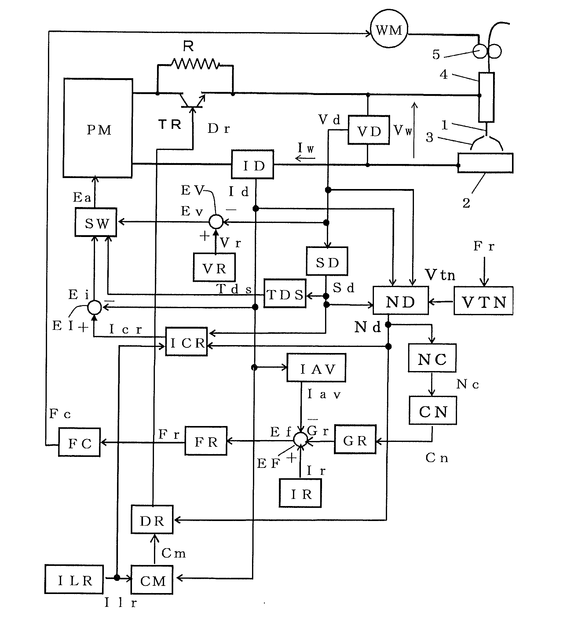
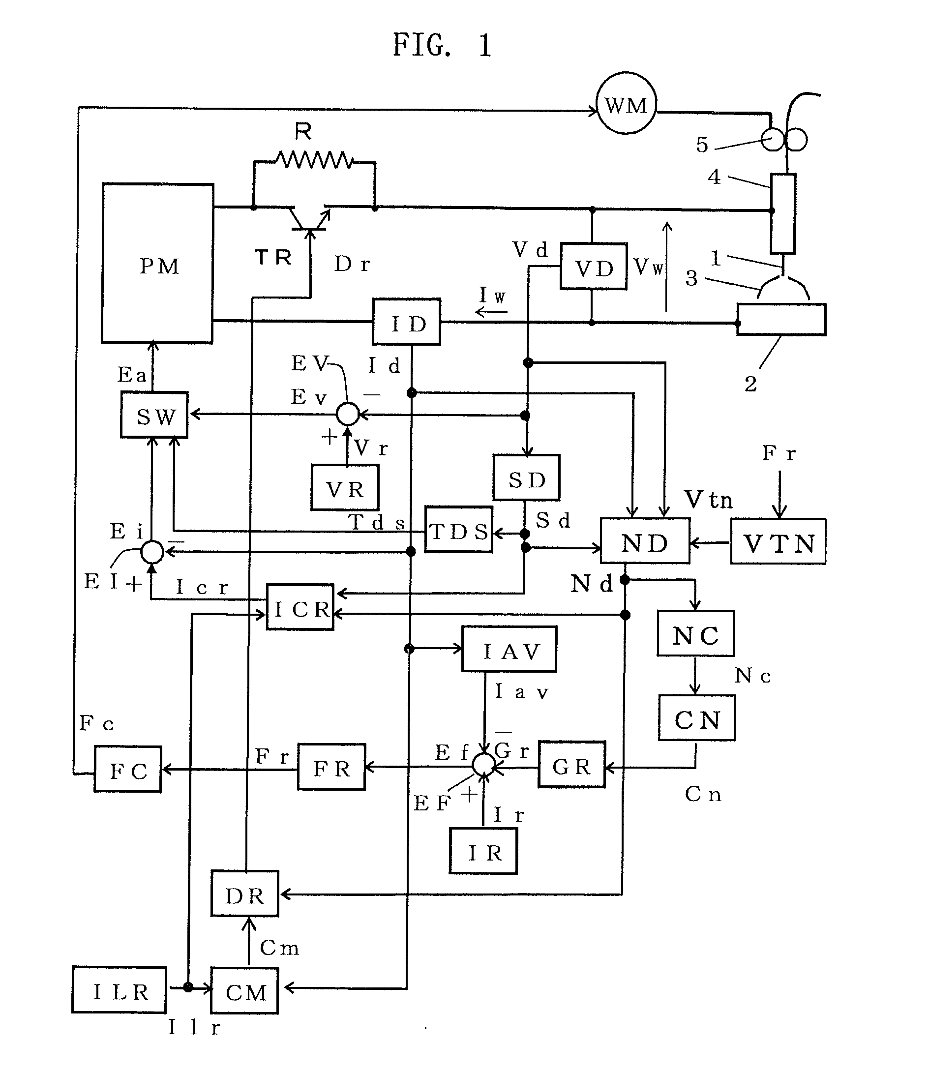
[0015]FIG. 1 is a block diagram of a welding power source for carrying out a consumable electrode arc welding method according to an embodiment of the present invention.

[0016]The welding power source includes a main circuit PM for connection to a three-phase, 200V or similar commercial power supply. The power source main circuit PM performs output control such as inverter control based on an error amplified signal Ea and outputs a welding voltage Vw and a welding current Iw to a welding torch 4 and a base material 2. The power source main circuit PM includes a primary rectifier for rectifying alternating current inputted from a commercial power supply, a smoothing capacitor for smoothing the direct current obtained by rectification, an inverter circuit for converting the smoothed direct current into a high-frequency alternating current, a high-frequency transformer fo...


PUM

PropertyMeasurementUnit
resistanceaaaaaaaaaa
currentaaaaaaaaaa
transient response timeaaaaaaaaaa

Abstract

A consumable electrode arc welding method includes the detecting of a constriction formed in a molten droplet of the welding wire so as to reduce the welding current, the detecting of a smoothed value of the welding current, and the feedback controlling of the feed rate of the welding wire so as to make the smoothed value of the welding current correspond to a predetermined current setting value. The constriction detection is performed repetitively in a predetermined cycle.
In each time of the repetition, the length of a constriction time, from the constriction detection till the arc generation, is measured. The number of constriction time lengths falling outside a predetermined range is counted. When the counted number is not less than a reference number, the transient response time of the feedback control is made longer.

Description

BACKGROUND OF THE INVENTION[0001]1. Field of the Invention[0002]The present invention relates to a consumable electrode arc welding method. In particular, the present invention relates to constriction detection control and wire feed rate variable control in a consumable electrode arc welding method.[0003]2. Description of the Related Art[0004]JP-A-2006-281219 discloses a technique related to consumable electrode arc welding. In the conventional consumable electrode arc welding, an arc generating state and a short-circuiting state repetitively occur between a welding wire and a base material. As a premonitory sign of regeneration of an arc from a short-circuiting state, a constriction forms in a molten droplet. The formation of a constriction is detected based on a change in the voltage (or resistance) between the welding wire and the base material. When a constriction is detected, the welding current is reduced sharply so that an arc is generated in a low current. This constriction ...

Claims


Application Information

Patent Timeline
Patent Type & Authority Applications(United States)
IPC IPC(8): H05B1/02
CPCH05B1/0202B23K9/073B23K9/095B23K9/173
Inventor TAKADA, KENTONAKAMATA, TOSHIAKI
Owner DAIHEN CORP
Why Eureka
Try Eureka