Self-tuning resonant power transfer systems

a resonant power transfer and self-tuning technology, applied in the direction of transformer/inductance circuits, circuit arrangements, inductances, etc., can solve the problems of limited size and power requirements of implanted devices, limited position within the body that can accommodate larger implants,

Active Publication Date: 2014-01-30
TC1 LLC
View PDF3 Cites 105 Cited by
  • Summary
  • Abstract
  • Description
  • Claims
  • Application Information

AI Technical Summary

Benefits of technology

[0008]A wireless power transfer system is provided, comprising a transmit resonator coupled to a voltage source and a first impedance matching network, and a receive resonator coupled to a second impedance matching network, the receive resonator being inductively coupled to the transmit resonator, the system being configured such that resonant frequencies of the system move towards an operating frequency of the system as a coupling coefficient between the transmit and receive resonators becomes smaller.

Problems solved by technology

Additionally, positions within the body are limited that can accommodate larger implanted devices, some of which are deep below the skin surface.
By implanting these devices directly under the skin, the size and power requirements of these implanted devices is limited if they are to be powered by a TET system.

Method used


Image

  • Self-tuning resonant power transfer systems
  • Self-tuning resonant power transfer systems
  • Self-tuning resonant power transfer systems

Examples


first embodiment

[0084]In a first embodiment, shown in FIG. 4, a TET system 100 comprises two resonant systems, a transmitter resonator 102 and a receiver resonator 104. Each of the resonant systems can be connected to a voltage divider circuit. Transmitter resonator 102 includes an inductor Lx and a capacitor Cx2 configured as a tank circuit. Receiver resonator 104 includes an inductor Ly and a capacitor Cy2 configured as a tank circuit. In order to excite each resonant system an impedance matching circuit can connect the transmitter resonator to the power source and the receiver resonator to the load. This way the load and power source only have to supply the real part of the power, and the reactive part of the power is handled by the impedance matching circuit.

[0085]In FIG. 4, the impedance matching circuits can comprise voltage dividers formed from capacitors. Voltage divider 106 can be coupled to transmitter resonator 102 and can comprise capacitor Cx1 and inductor Ls, coupled to voltage source...

second embodiment

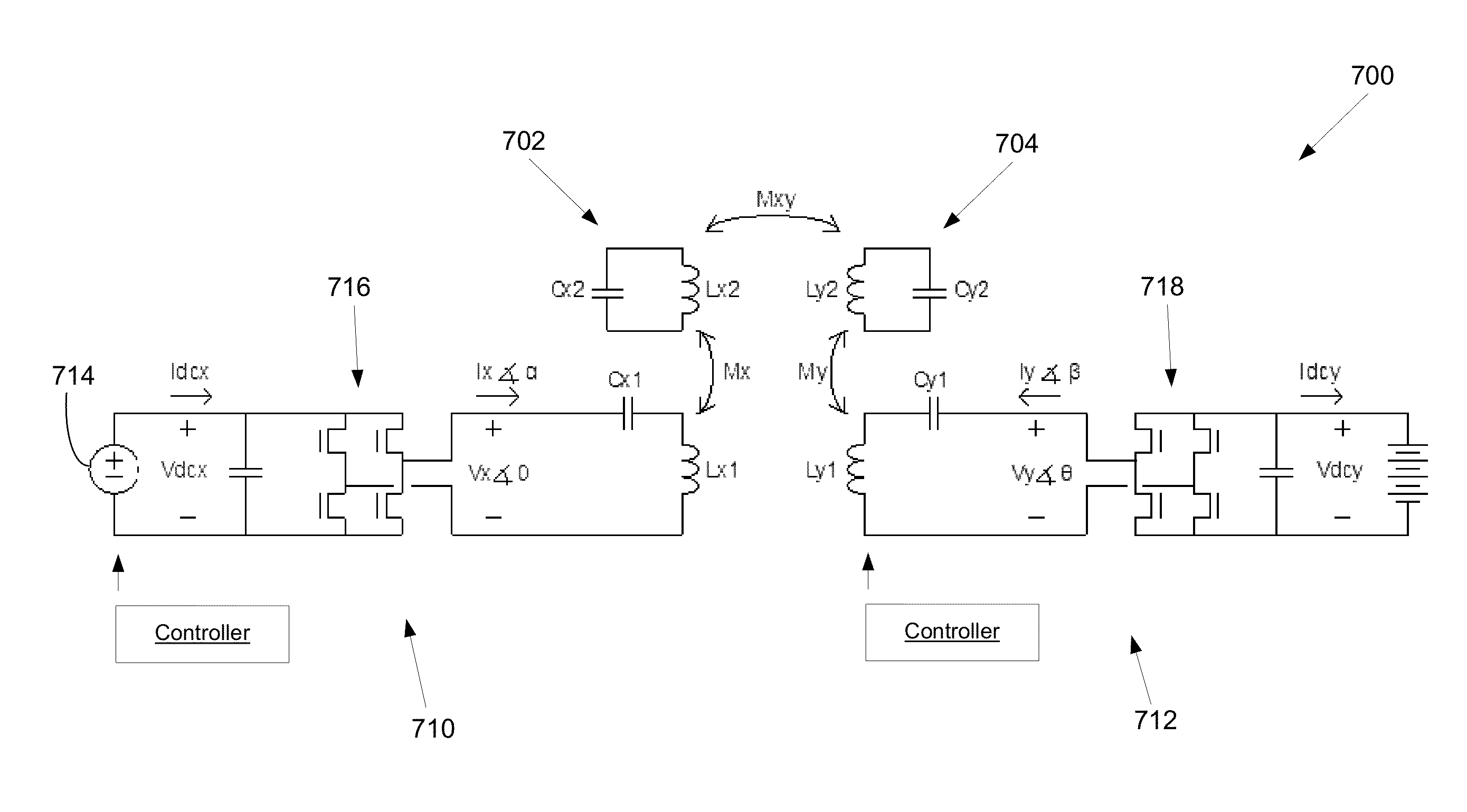
[0087]In TET system 200, shown in FIG. 5, transmitter resonator 202 includes an inductor Lx2 and a capacitor Cx2 configured as a tank circuit. Receiver resonator 204 includes an inductor Ly2 and a capacitor Cy2 configured as a tank circuit. The impedance matching circuits can comprise transformer circuits. Transformer circuit 210 can be inductively coupled to transmitter resonator 202 and can include capacitor Cx1 and inductor Lx1 coupled to voltage source Vs. Transformer circuit 212 can be inductively coupled to receiver resonator 204 and can comprise capacitor Cy1 and inductor Ly2, coupled to the Load.

[0088]In FIG. 5, the two coils on the transmitter can act like a transformer so that the voltage on Lx1 is much smaller than the voltage on Lx2. Lx2 and Cx2 make up the transmitter resonator, and Lx1 and Cx1 act as an exciter to keep the resonance going.

[0089]Both variations described in FIGS. 4 and 5 can be designed to work equally well. There will be trade-offs relating to the deta...


PUM

PropertyMeasurementUnit
poweraaaaaaaaaa
impedanceaaaaaaaaaa
resonant frequenciesaaaaaaaaaa

Abstract

Systems and designs for tuning a wireless power transfer system are provided, which may include any number of features. In one embodiment, a wireless power transfer system can be configured such that resonant frequencies of the system move towards an operating frequency of the system as a coupling coefficient between the transmit and receive resonators becomes smaller. In another embodiment, a receive controller can be configured to control a current delivered to a DC load by comparing an actual current at the DC load to a current requested by the DC load and adjusting an angle or a magnitude of a voltage at the DC load to match the requested current. In another embodiment, a rectifier circuit can act as a controlled voltage source and be configured to tune resonant frequencies between the transmit resonator and the receive resonator. Methods of use are also provided.

Description

CROSS-REFERENCE TO RELATED APPLICATIONS[0001]This application claims the benefit of U.S. Provisional Patent Application No. 61 / 676,637, filed on Jul. 27, 2012, titled “Self-Tuning Resonant Power Transfer Systems”, U.S. Provisional Patent Application No. 61 / 790,682, filed on Mar. 15, 2013, titled “Self-Tuning Resonant Power Transfer Systems”, and U.S. Provisional Patent Application No. 61 / 676,674, filed on Jul. 27, 2012, titled “Resonant Power Transfer Systems Having Synchronous Rectification”.INCORPORATION BY REFERENCE[0002]All publications and patent applications mentioned in this specification are herein incorporated by reference to the same extent as if each individual publication or patent application was specifically and individually indicated to be incorporated by reference.FIELD[0003]The field relates generally to resonant wireless power transfer systems, and more specifically to implantable resonant wireless power transfer systems.BACKGROUND[0004]Many implantable medical dev...

Claims


Application Information

Patent Timeline
Patent Type & Authority Applications(United States)
IPC IPC(8): H01F38/14
CPCH01F38/14H02J50/12H02J50/30
Inventor PETERSEN, ETHANHANSEN, JOHN FREDDY
Owner TC1 LLC
Why Eureka
Try Eureka