Interferometer, optical assembly and method of mounting same

a technology of interferometers and optical assemblies, applied in the field of optical devices, can solve the problems of inaccuracy of optical measurements, distortions due, and cost of meticulous alignment, and achieve the effects of reducing and/or eliminating tilting, bending, warping, and distorting

Active Publication Date: 2014-01-30
PLX
View PDF0 Cites 13 Cited by
  • Summary
  • Abstract
  • Description
  • Claims
  • Application Information

AI Technical Summary

Benefits of technology

[0019]Another object of the invention is to provide an improved interferometer and/or optical assembly for an optical structure which causes minimal external stresses to, and reduces and/or eliminates tilting, bending, warping, distorting, etc. of, the reflective and refractive surfaces, such as the beamsplitter, compensator and mirror(s) of the interferometer and/or interferometer optical assembly.
[0020]A further object of the invention is to provide an improved interferometer and/or optical assembly that causes minimal external stresses to, and reduces and/or eliminates tilting, bending, wa...

Problems solved by technology

Such forces and resultant distortions introduce inaccuracies into the optical measurements.
A similarly pervasive issue concerns distortions due to changes in the thermal environment.
The trouble with these prior art interferometers and optical assemblies arises from the costs involved in meticulously aligning the optical elements, the necessity for active subsystems to maintain the alignment, and subsequent costs to service and readjust the interferometer if shocks and vibrations have introduced uncompensated misalignment.
However, it is not...

Method used


Image

  • Interferometer, optical assembly and method of mounting same
  • Interferometer, optical assembly and method of mounting same
  • Interferometer, optical assembly and method of mounting same

Examples


Embodiment Construction

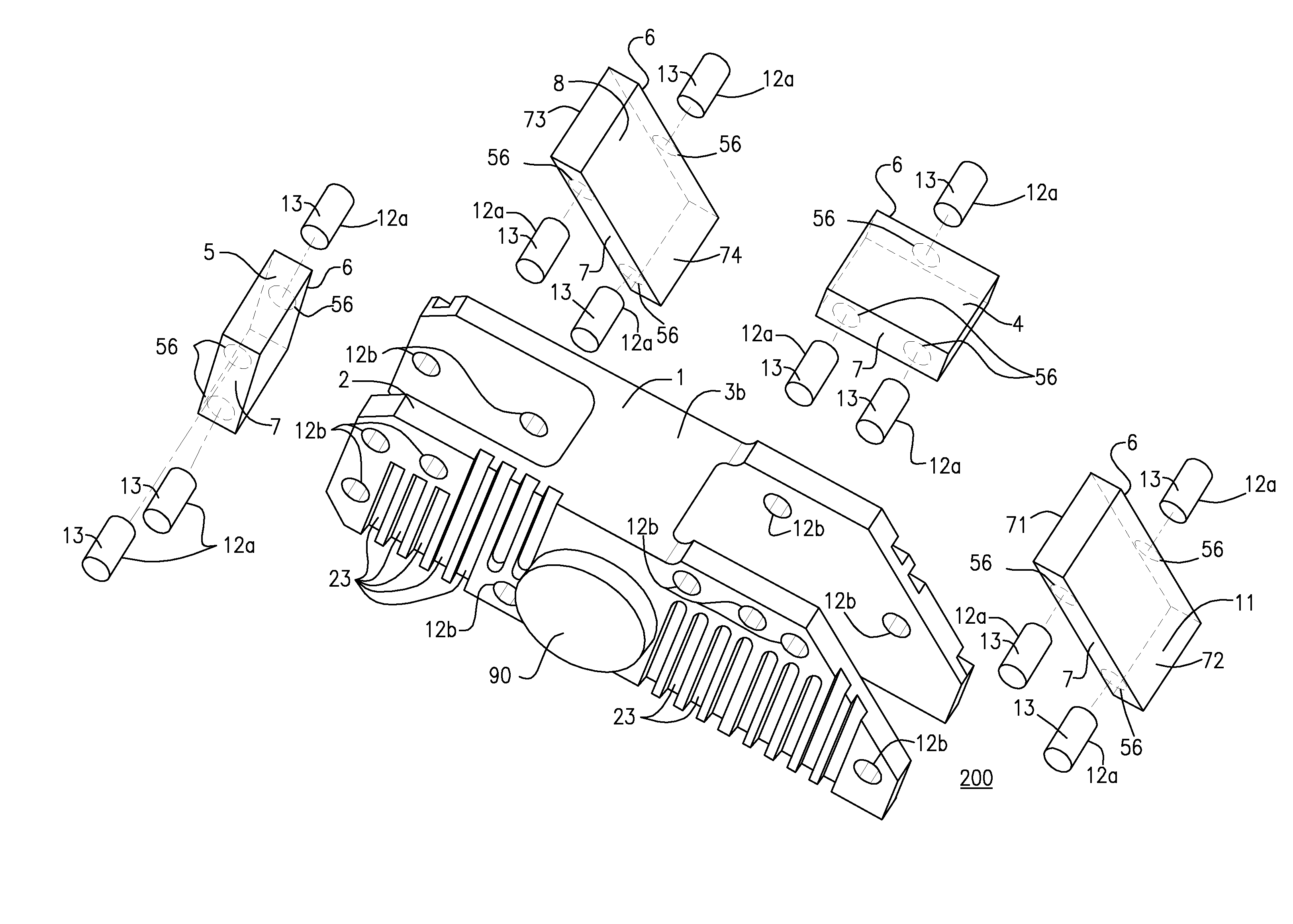
[0038]An improved interferometer, optical assembly, and method of mounting same, are disclosed herein. The interferometer and / or optical assembly may include a beamsplitter and / or a compensator made from at least a first material and a frame having at least a first plate and a second plate made of at least a second material. Preferably, the first and second materials have identical or substantially the same coefficients of thermal expansion, or have coefficients of thermal expansion that are as close as practicable to each other, such that one or more components of the interferometer and / or optical assembly, including, but not limited to, the beamsplitter, the compensator, etc., have limited or no exposure to at least one of bending, warping, tilting and distorting. Preferably, one or more components of the interferometer and / or the optical assembly, such as, but not limited to, the beamsplitter, the compensator, etc., are kinematically connected to the frame using an apparatus havi...


PUM

PropertyMeasurementUnit
Temperatureaaaaaaaaaa
Areaaaaaaaaaaa
Stress optical coefficientaaaaaaaaaa

Abstract

A frame for optics used in interferometers that may include different materials having substantially similar, identical, or as close as practicable coefficients of thermal expansion from the material(s) used to make the beamsplitter and/or compensator without warping, bending, tilting or distorting the optics. The beamsplitter and/or compensator are mounted onto the frame of the interferometer using a three-point method of mounting, preferably using three pins for each component. Preferably, the pins are made of the same material as the beamsplitter and compensator, and all three components are made of Potassium Bromide (“KBr”) or Calcium Fluoride (“CaF2”) such that the optic instrument can operate to scan into the mid or far infrared. Stability in optical alignment is therefore achieved without requiring the optic instrument include only one material. The invention provides stability in situations where it is not possible to utilize a single material for every component of the interferometer.

Description

CROSS REFERENCE TO RELATED APPLICATIONS[0001]This application is a continuation of U.S. patent application Ser. No. 13 / 560,510, filed on Jul. 27, 2012, the entirety of which is incorporated herein by reference.BACKGROUND OF THE INVENTION[0002]This invention relates to the field of optical devices, and, more particularly, to interferometers, including monolithic interferometers, optical assemblies, and methods of mounting same. Such interferometers or interferometer optical assemblies provide stability in optical alignment by, among other factors, using a single material. The present invention provides stability in situations where it is not possible to utilize a single material for every component of the interferometer or optical assembly.[0003]Fourier transform infrared (“FTIR”) spectrometers are well known in the art. Michelson interferometers function by splitting a beam of electromagnetic radiation into two separate beams via a beam splitter. Each beam travels along its own path...

Claims


Application Information

Patent Timeline
IPC IPC(8): G02B7/192G02B7/182B23P17/04G01B9/02
CPCG01B9/02051G01B9/02058G01J3/0202G01J3/0286G01J3/45G02B1/02G02B27/1073G02B27/144Y10T29/49826Y10T29/49895
Inventor BLEIER, ZVIJACOBSON, ALEXANDERVISHNIA, ITAI
Owner PLX
Why Eureka
Try Eureka