
Process of manufacturing crystalline silicon solar cell

a technology of crystalline silicon and solar cells, which is applied in the field of manufacturing can solve the problems of increasing the cost of solar cells, the burden on the environment, and the reduction of global storage capacity and price, and achieve the effect of improving the photoelectric conversion efficiency of crystalline silicon solar cells

Inactive Publication Date: 2014-02-06
INST NUCLEAR ENERGY RES ROCAEC
View PDF0 Cites 11 Cited by
  • Summary
  • Abstract
  • Description
  • Claims
  • Application Information

AI Technical Summary

Benefits of technology

The invention provides a way to make a crystalline silicon solar cell that has a simplified chemical process and higher photoelectric conversion efficiency without adding any extra steps to the existing manufacturing process.

Problems solved by technology

Large-scale use of fossil fuels leads to significant decrease in global storage capacity and rise in prices.
Large amount of pollutant emission causes global warming and climate anomalies, and other issues about posing threats to human living environment as well.
Those chemicals produce large amount of organic acidic and alkali gas and liquid waste, resulting in the burden on the environment.
Therefore, the currently available solar cells cannot be regarded as green products.

Method used


Image

  • Process of manufacturing crystalline silicon solar cell
  • Process of manufacturing crystalline silicon solar cell
  • Process of manufacturing crystalline silicon solar cell

Examples


Embodiment Construction

[0044]The aforementioned illustrations and following detailed descriptions are exemplary for the purpose of further explaining the scope of the present invention. Other objectives and advantages related to the present invention will be illustrated in the subsequent descriptions and appended tables.

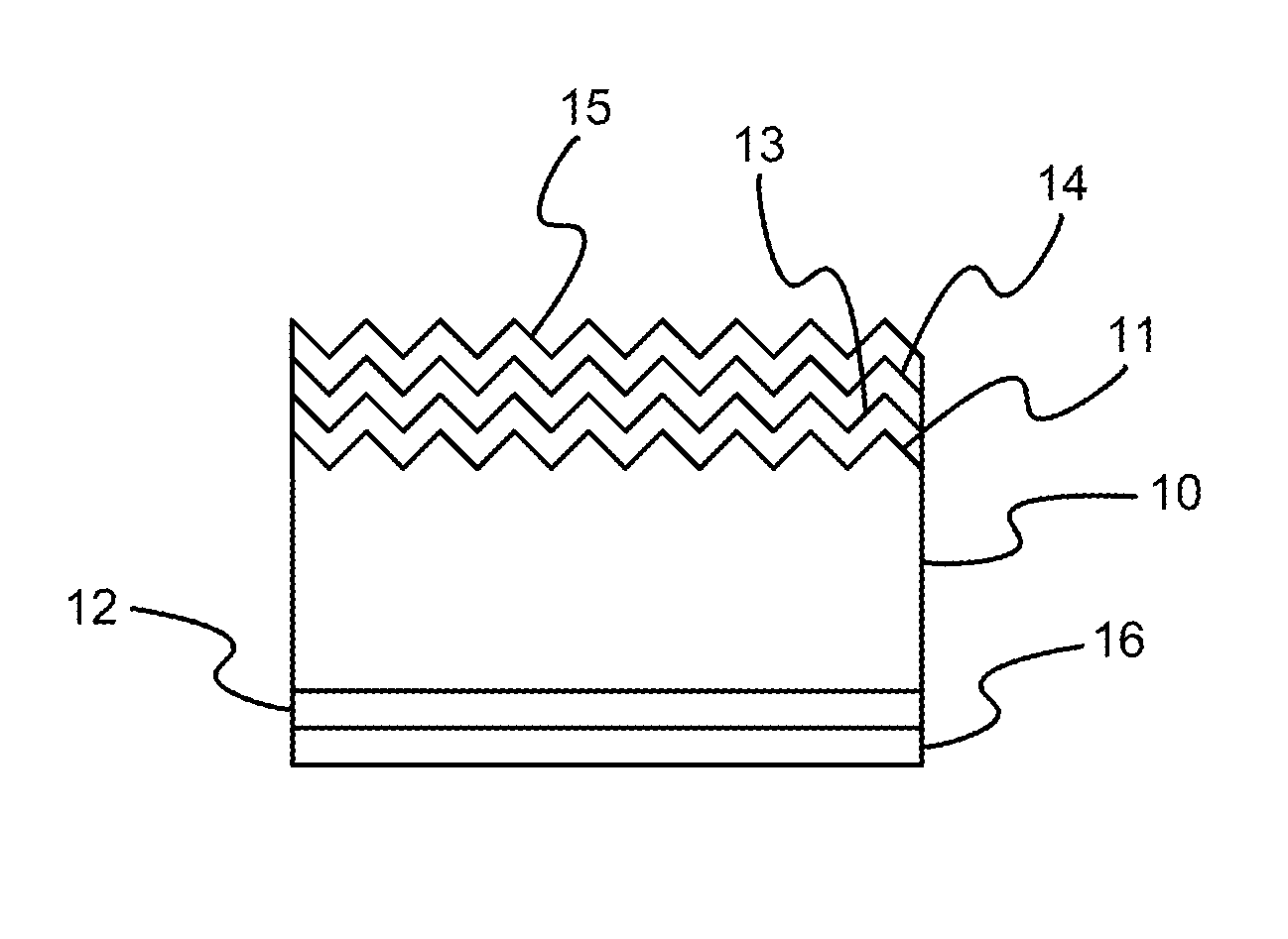
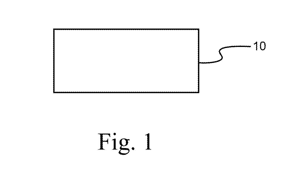
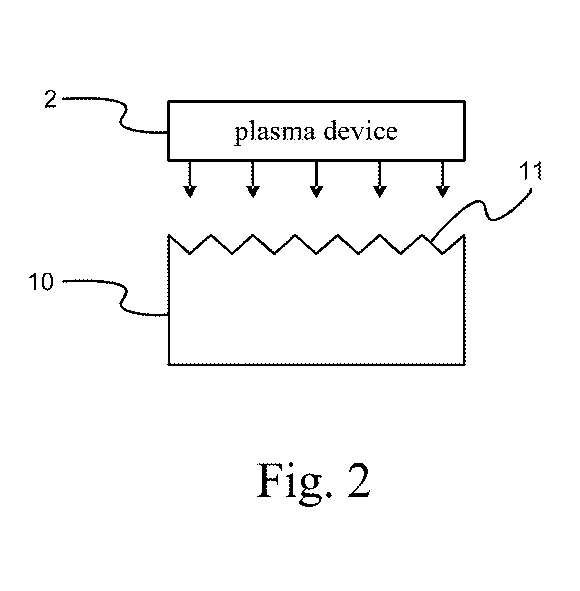
[0045]FIG. 1 is a schematic view of Step 1 of a process of manufacturing a crystalline silicon solar cell according to the invention. FIG. 2 is a schematic view of Step 2 of a process of manufacturing a crystalline silicon solar cell according to the invention. FIG. 3 is a schematic view of Step 3 of a process of manufacturing a crystalline silicon solar cell according to the invention. FIG. 4 is a schematic view of Step 4 of a process of manufacturing a crystalline silicon solar cell according to the invention. FIG. 5 is a schematic view of Step 5 of a process of manufacturing a crystalline silicon solar cell according to the invention. FIG. 6 is a schematic view of Step 6 of a process of...


PUM

PropertyMeasurementUnit
energyaaaaaaaaaa
mechanicalaaaaaaaaaa
areaaaaaaaaaaa

Abstract

A process of manufacturing a crystalline silicon solar cell includes forming a rough surface on a surface of the crystalline silicon wafer and an Al2O3 film is coated on a non-rough surface thereof. A single-sided n diffusion layer and phosphosilicate glass film are formed. An anti-reflection layer SiNx film is formed on a top surface of the phosphosilicate glass film. An Al metallic film is formed as a back ohmic electrode on the Al2O3 film. The local area of the anti-reflection layer SiNx film and the phosphosilicate glass film is melted and removed to form a local area of n+-Si layer. Then, an Al—Si back ohmic contact electrode is formed between the Al metallic film and the crystalline silicon wafer. A front ohmic contact electrode is formed on the molten and removed area of the antireflection layer SiNx film and the phosphosilicate film by light-induced plating.

Description

BACKGROUND OF THE INVENTION[0001]1. Field of the Invention[0002]The present invention relates to a process of manufacturing a crystalline silicon solar cell, and more particularly, to a process which not only offers the simplified chemical process with minimal problems about dealing with follow-up chemical solutions, but also achieves the improvement on the photoelectric conversion efficiency of the crystalline silicon solar cell, without adding any extra processing steps to the existing standard process of manufacturing the crystalline silicon solar cell.[0003]2. Description of Related Art[0004]The sun is the source of all energy on Earth. Most of currently known energies such as oil, coal, natural gas, water power, solar energy, wind power, photosynthesis energy, and ocean energy are directly or indirectly from the sun. The energy (˜5×10²⁰ J) generated by irradiating the sunlight over the entire Earth's surface for one hour is enough for the whole human being to use about 1 year. ...

Claims


Application Information

Patent Timeline
Patent Type & Authority Applications(United States)
IPC IPC(8): H01L31/18
CPCH01L31/022425H01L31/02363H01L31/068H01L31/1804Y02E10/547Y02P70/50
Inventor YANG, TSUN-NENG
Owner INST NUCLEAR ENERGY RES ROCAEC
Learn More