Decoupled parallel meshing in computer aided design

a parallel meshing and computer aided design technology, applied in the field of decoupled parallel meshing in computer aided design, can solve the problems of many opportunities for parallelism lost, coarse meshes are in general more difficult to create than fine ones, and memory is a severe limitation of such codes, so as to achieve better scalability

Inactive Publication Date: 2014-02-06
FUJITSU LTD
View PDF3 Cites 31 Cited by
  • Summary
  • Abstract
  • Description
  • Claims
  • Application Information

AI Technical Summary

Benefits of technology

[0039]As compared to the technology described in US2007011646A1, which consists of a way of achieving parallel meshing based on the domain decomposition approach, aspects of the present invention provide a feasible implementation of the decoupled domain decomposition method based on CAD operations (which in US2007011646A1 is only described at an abstract level), extension to assembly models and the added level of parallelism resulting from dealing with such models, and automation for finding the best meshing parameters.
[0040]As compared to the parallelization approach applied in all parallel meshers presently available on the market, which are the same as or similar to that descr

Problems solved by technology

With a mesh of the order of 1 million elements requiring in the order of 1 GB of memory to create, it is clear that memory is a severe limitation for such codes.
The main drawback of this approach is that, for complex geometries, coarse meshes are in general more difficult to create than fine ones, since the small features of the geometry are more easily approximated by small elements rather than large ones.
Hence, for complex geometries, the initial 2D mesh will need to be fine rather than coarse, which will become a major bottleneck of the algorithm.
However, this document describes the operation at an abstract level and does not give any way in which it can be actually implemented.
Another important issue which has not been addressed in any prior art so far is the fac

Method used


Image

  • Decoupled parallel meshing in computer aided design
  • Decoupled parallel meshing in computer aided design
  • Decoupled parallel meshing in computer aided design

Examples


Embodiment Construction

[0074]Before describing an embodiment which brings together the different aspects of the present invention, the terms used in the present application will now be defined.
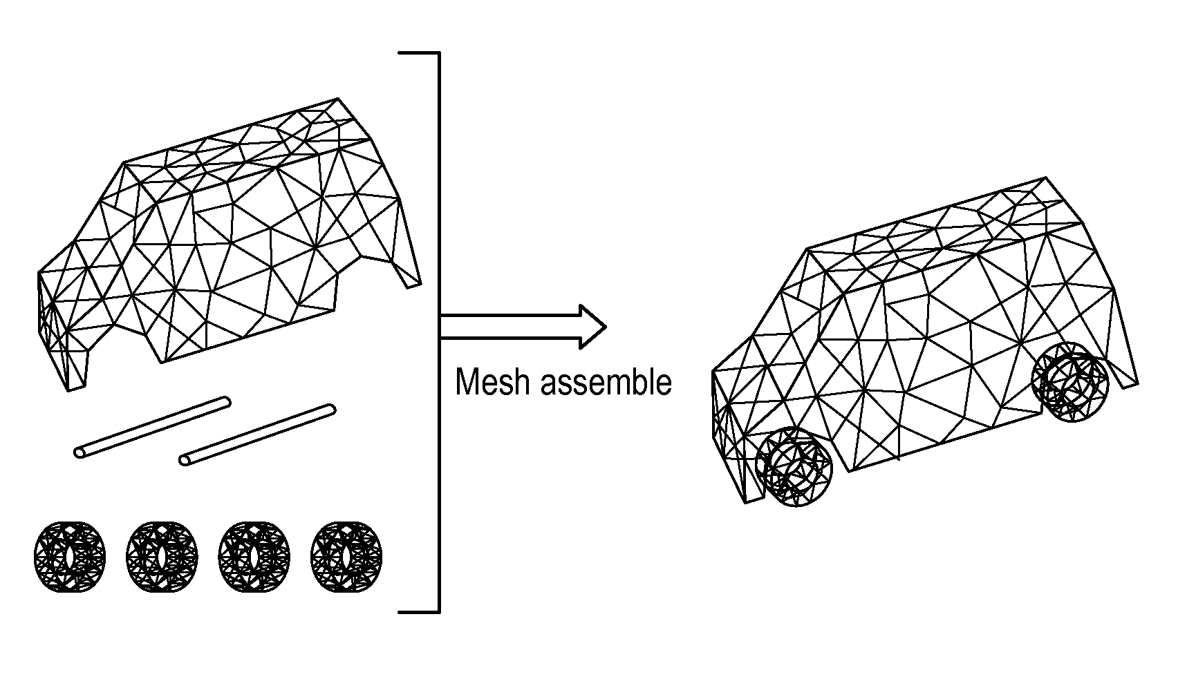
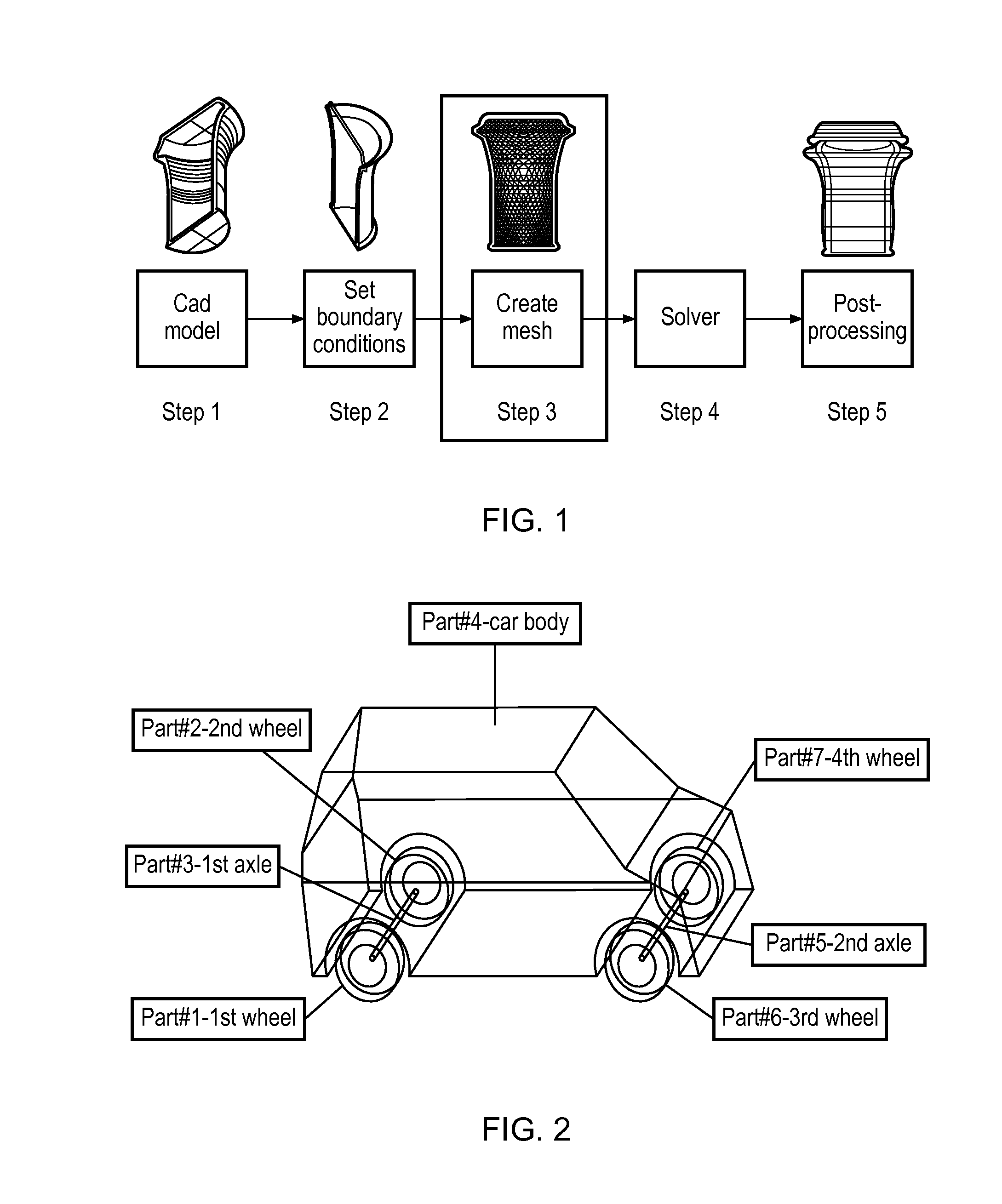
Assembly Model

[0075]An assembly model is a CAD model consisting of multiple solids, which may or may not be in physical contact with each other. A simple assembly model consisting of seven parts, labelled Parts#1 to #7, is shown in FIG. 2. Real-world assembly models used in industry, which this invention targets, can have hundreds or thousands of parts, of different shapes and sizes. Throughout the present application, the term part will have the meaning of a single solid component of an assembly model. For the sake of consistency, if the input CAD file consists of a single solid, we will refer to it as an assembly with one part.

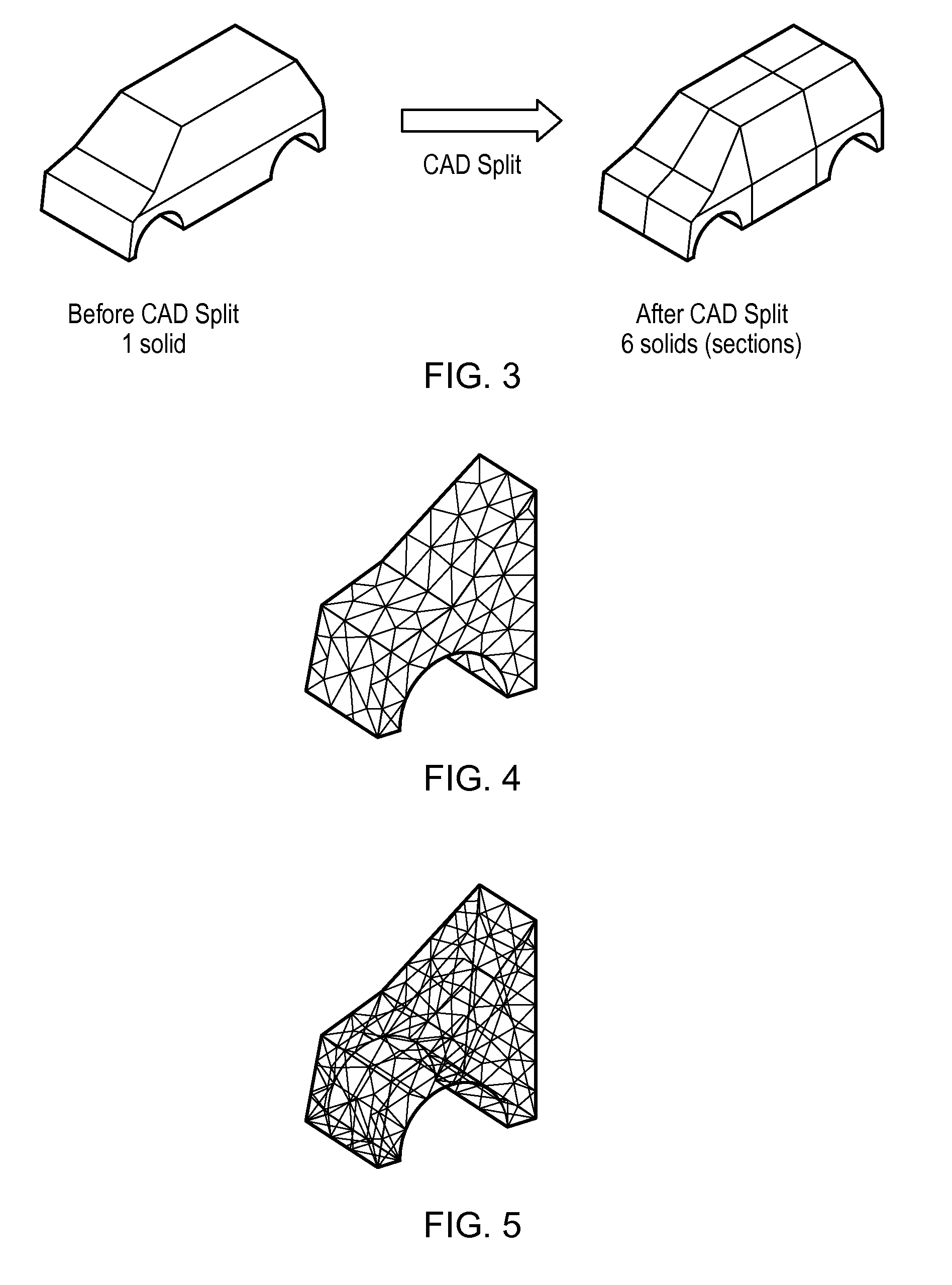
CAD Splitting (Cutting, Partitioning)

[0076]In the present application CAD splitting is defined as the operation of splitting / cutting / partitioning a solid into a number of sections. For examp...


PUM


Abstract

In a meshing method for use in a computer-aided design (CAD) or computer-aided engineering (CAE) system, in which one or more serial meshing units are used to carry out a decoupled parallel meshing process in respect of all parts of a CAD assembly model, input parameters for the meshing process automatically, for each part to be processed, are set using live runtime information about the meshing process for the part concerned, such as information about the outcome of previous attempts to carry out the meshing process of the part.

Description

CROSS REFERENCE TO RELATED APPLICATIONS[0001]This application claims the benefit of European Application No. 12173469.3, filed Jun. 25, 2012, the disclosure of which is incorporated herein by reference.BACKGROUND OF THE INVENTION[0002]The present invention relates to decoupled parallel meshing in computer-aided design (CAD), and in particular to methods, apparatus and programs for use at different stages of a decoupled parallel meshing process.[0003]Computed Aided Engineering (CAE), the use of computer software for the purpose of modelling and simulating the behaviour of products in order to improve their quality, has become nearly ubiquitous in the manufacturing industry. Areas covered by CAE include, but are not limited to, stress and thermal analysis, fluid dynamics and kinematics.[0004]As shown in FIG. 1 of the accompanying drawings, a typical CAE process starts with a Computer Aided Design (CAD) file which represents the geometrical model of the object that is analyzed (step 1)...

Claims


Application Information

Patent Timeline
IPC IPC(8): G06F17/50G06F9/48
CPCG06F9/4881G06F17/50G06T17/005G06T17/20G06T19/20G06T2219/2008G06F30/23G06F30/15G06F30/00G06F2111/02
Inventor GEORGESCU, SERBANCHOW, PETERSAKAIRI, MAKOTOSAKAI, HIDEHISA
Owner FUJITSU LTD
Why Eureka
Try Eureka