Solid state light sources with common luminescent and heat dissipating surfaces

a technology of luminescent and heat dissipation surface, which is applied in the direction of semiconductor devices, light sources, lighting and heating equipment, etc., can solve the problemsrequiring more expensive processing, and most consumers are not willing to pay more. , to achieve the effect of reducing the cost of solid state light sources

Active Publication Date: 2014-02-13
GOLDENEYE
View PDF0 Cites 34 Cited by
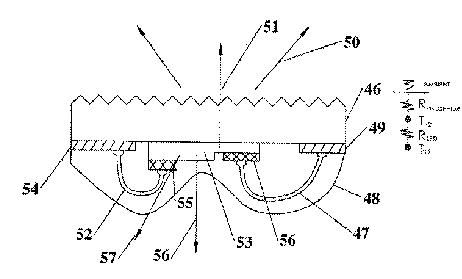
  • Summary
  • Abstract
  • Description
  • Claims
  • Application Information

AI Technical Summary

Benefits of technology

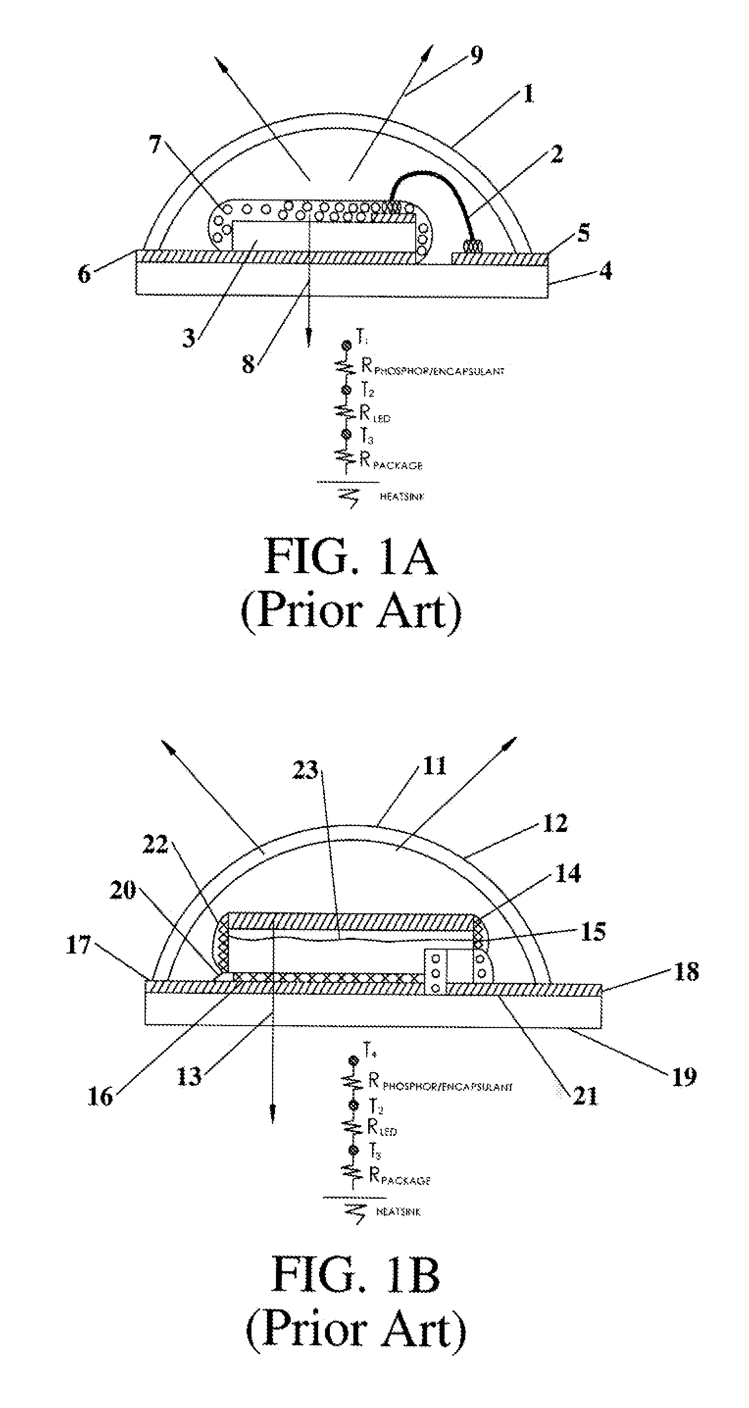
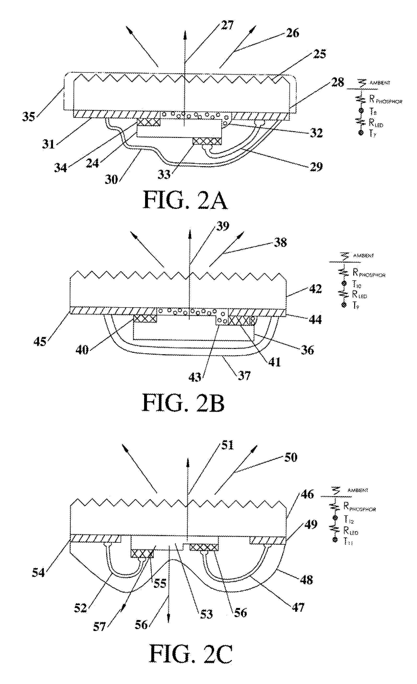
[0005]This invention relates to solid state light sources based on LEDs mounted to and in thermal contact to light transmitting thermally conductive elements, which have sufficient surface area to provide convective and radiative cooling to dissipate the majority of the heat generated by the LEDs. Briefly, and in general terms, the present invention resides in a self cooling light source comprising at least one light-emitting diode (LED) and at least one light transmitting thermally conductive element to which the LED is mounted, the element having a heat emitting surface through which most of the heat from the LED is dissipated. Ideally, the light source is structured to redirect light emitted by the LED to pass through and exit from the light transmitting thermally conductive element through its heat emitting surface. In most cases the light transmitting thermally conductive material is also partially reflective and is sometimes referred herein as a reflective / transmissive (or reflective and transmissive light transmitting) thermally conducting element. Also the term “translucent” is used herein to describe elements that are both partially reflective and partially transmitting of light incident on them but also capable of waveguiding and scattering the light incident within the element. More economical, self-cooling solid state light sources can be realized by utilizing lower light transmitting (i.e. mostly reflective) thermally conductive translucent elements. Mostly reflective is used herein to describe light transmitting elements, which have higher light reflectivity than light transmissivity. Remarkably, it has been found when mostly reflective and, therefore, low (less than 16% to 20%) light transmitting thermally conductive elements are arranged to form a closed cavity or enclosure (which causes the light that is emitted by the LEDs, mounted to the inside surfaces of the elements, to reflect and recycle inside the thus formed light recycling cavity) that a high percentage (e.g. >80%) of the light emitted by the LEDs eventually is transmitted and extracted through one or more of the mostly reflective partially light transmitting thermally conductive elements and thereby is emitted from the outside surfaces of the cavity. All of the outside surfaces of the cavity are thereby luminescent (light emitting) and they also simultaneously dissipate the heat generated by the LEDs via convection and radiation. This creates a visually pleasing, very uniform and omnidirectional light source without requiring an appended heat sink. Because there is no need for an appended heat sink, there is no blocking of the light from any of the emitting sides of the source, creating a truly omnidirectional light source. Optionally, a reflector may be used with at least one LED and at least one thermally conductive translucent element to form the light recycling cavity to create a directional light source emitting from one or more of the sides (e.g. emitting into a hemisphere vs. a solid angle).
[0006]The electrical interconnect to the LEDs as well as other semiconductor devices can be integrated onto the thermally conductive translucent elements. The electrical interconnects can be highly reflective or optionally transparent electrical conductive traces on the thermally conductive translucent elements. In one embodiment of the invention, multiple, partially optically reflective and partially optically transmissive, thermally conductive elements are used to form a light recycling cavity, reflecting and light recycling emitted by the LEDs mounted to the interconnects on the thermally conductive translucent elements that form the cavity. Due to the multiple light reflections therein, a portion of the light emitted from each LED will be transmitted through one or more of the thermally conductive reflective and transmissive elements making up the cavity. The term ‘mostly reflective’ as used herein refers to thermally conductive elements that reflect over 50% of the light initially incident on them. Optionally, more costly higher in line light transmission (greater than 70%) materials may be utilized (e.g. transparent alumina oxide, TPA). These are typically less than 30% reflective. Wavelength conversion can be accomplished by: phosphor coatings or caps on the LEDs, wavelength conversion elements that are ceramic or organic and coated or bonded onto the thermally conductive translucent elements or optionally incorporated into the thermally conductive translucent elements. Light sources constructed, as described, with light transmitting (optionally translucent) thermally conductive elements or more reflective thermally conductive elements can completely or partially eliminate the need for any additional heat sinks by efficiently transferring and spreading out the heat generated in the LED over an area sufficiently large enough such that convective and radiative means can be used to cool the device.
[0007]Moreover, the use of lower light transmitting materials permits the use of higher thermal conductivity materials, which reduce the thermal resistance between the LED p-n junction (where the heat is generated) and the light emitting surfaces of the light source where the heat is dissipated. This in effect places the emitting surface to be cooled at a higher temperature (closer to the LED junction temperature), which enables more efficient radiative and convective cooling to ambient.

Problems solved by technology

Most consumers are not willing to pay more (initially) for eventual savings later.
However, reducing the cost of solid state light sources has been a big challenge for lighting companies.
However, to achieve high transparency in ceramic materials usually requires more expensive processing.
However if the cost of processing the light transmissive thermally conductive materials is high, this becomes a significant factor in the cost of the light source.
This small temperature difference not only eliminates most of the radiative cooling but also requires that the heat sink be fairly large (and heavy) to provide enough surface area to effectively cool the LEDs.
In general, the added weight of the heat sink and / or active cooling increases costs for shipping, installation, and in some cases poses a safety risk for overhead applications.

Method used


Image

  • Solid state light sources with common luminescent and heat dissipating surfaces
  • Solid state light sources with common luminescent and heat dissipating surfaces
  • Solid state light sources with common luminescent and heat dissipating surfaces

Examples


Embodiment Construction

[0037]According to the present invention as practiced herein, a conductive interconnect (transparent or reflective) is deposited on translucent thermally conductive elements (e.g. alumina (Al2O3), transparent alumina (TPA), Spinel, Sapphire, etc.) This can be done lithographically, or more preferred, via screen printing. LEDs or LEDs on surface mountable ceramic substrates (also referred herein as LED packages) are mounted (e.g. via soldering or conductive adhesives) to the interconnect on the translucent thermally conductive elements. It is preferred that the mounting method establish a low thermal resistant contact from the LED to the light transmitting thermally conductive element. Light emitted by the LEDs is directed to the thermally conductive translucent elements where it passes through and is emitted by the thermally conductive light transmitting (and thereby light emitting luminescent) element. The light transmitting thermally conductive elements have surface areas sufficie...


PUM


Abstract

A solid state light source with LEDs in thermal contact to thermally conductive translucent elements where light emitted from the LEDs is directed to emerge from the heat dissipating surfaces of the elements. The thermally conductive translucent elements are arranged or combined with a reflector to form a light recycling cavity. The outside surfaces of the thermally conductive translucent elements forming the cavity become luminescent as the light emitted by the LEDs on the inside of the cavity is continually reflected and recycled until a very high percentage of the light emitted by the LEDs is eventually transmitted through and emitted uniformly and omnidirectionally. Simultaneously, the heat from the LEDs conducts through and to the luminescent outside surfaces of the elements of the cavity, which radiatively and convectively cool the light source thereby eliminating the need for bulky appended heat sinks.

Description

CROSS-REFERENCE TO RELATED APPLICATIONS[0001]This application is a continuation in part of U.S. application Ser. No. 13 / 572,608 filed on Aug. 10, 2012, which claims benefit of U.S. Provisional Application Ser. No. 61 / 574,925, filed on Aug. 11, 2011, which is herein incorporated by reference. This application also claims the benefit of U.S. Provisional Patent Application No. 61 / 957,768, filed Jul. 10, 2013, which is also herein incorporated by reference.BACKGROUND OF THE INVENTION[0002]Solid State light sources based on light emitting diode (LED) technology offer the promise of energy savings over incandescent and fluorescent lighting without the toxic materials utilized in fluorescent or organic light emitting diode (OLED) light sources.[0003]However to achieve widespread adoption and acceptance of solid state lighting (based on inorganic LEDs) requires that it be competitively priced to compete with incandescent and mercury filled fluorescent light sources. Even with its greener at...

Claims


Application Information

Patent Timeline
Patent Type & Authority Applications(United States)
IPC IPC(8): H01L33/64
CPCH01L33/642H01L33/501H01L33/502H01L33/641H01L24/73H01L2224/48091H01L2224/48227H01L2224/48464H01L2224/49107H01L2224/8592H01L2224/45144H01L2924/12041H01L2924/01322H01L2924/12042H01L2924/12044F21V29/505F21K9/20F21K9/60F21Y2115/10F21V7/24H01L2924/00014H01L2924/00H01L33/64H01L2924/0002F21S8/046F21S8/04H01L33/50F21V23/02
Inventor LIVESAY, WILLAIM R.ZIMMERMAN, SCOTT M.ROSS, RICHARD L.DEANDA, EDUARDO
Owner GOLDENEYE
Why Eureka
Try Eureka