Nerve stimulation techniques

a nerve stimulation and nerve technology, applied in the field of nerve stimulation, can solve the problems of inability to provide a continuous path for current applied by the electrode contact surface during the excessive period, and achieve the effects of preventing nerve migration, good electrical contact, and preventing damage to the nerv

Inactive Publication Date: 2014-02-13
MEDTRONIC INC
View PDF22 Cites 161 Cited by
  • Summary
  • Abstract
  • Description
  • Claims
  • Application Information

AI Technical Summary

Benefits of technology

[0308]In some embodiments of the present invention, an electrode assembly for applying current to tubular body tissue, such as a nerve, comprises one or more electrode contact surfaces fixed to a cuff. The cuff is shaped so as to define a plurality of recesses that extend radially outwardly from an innermost surface of the cuff surrounding a longitudinal axis of the cuff. Typically, the cuff is recessed in at least one radially outward direction at every longitudinal location along its entire length. The recesses may serve to prevent damage to the nerve by allowing the nerve to swell in at least one radial direction into at least one of the recesses, along the entire length of the cuff. Providing the recesses generally does not have a material impact on the activation function achieved by the electrode assembly.
[0309]Typically, each of the recesses has a length along the cuff that is less than the entire length of the cuff, e.g., less than 50% or 25% of the length of the cuff. This design generally prevents migration of the nerve over time into the recesses, away from the center of the cuff, as might occu

Problems solved by technology

In addition, because longitudinally adjacent recesses extend in different radially directions, the recesses do not provide

Method used


Image

  • Nerve stimulation techniques
  • Nerve stimulation techniques
  • Nerve stimulation techniques

Examples


Embodiment Construction

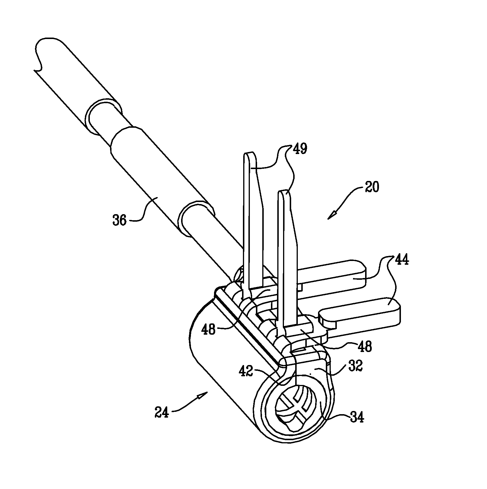
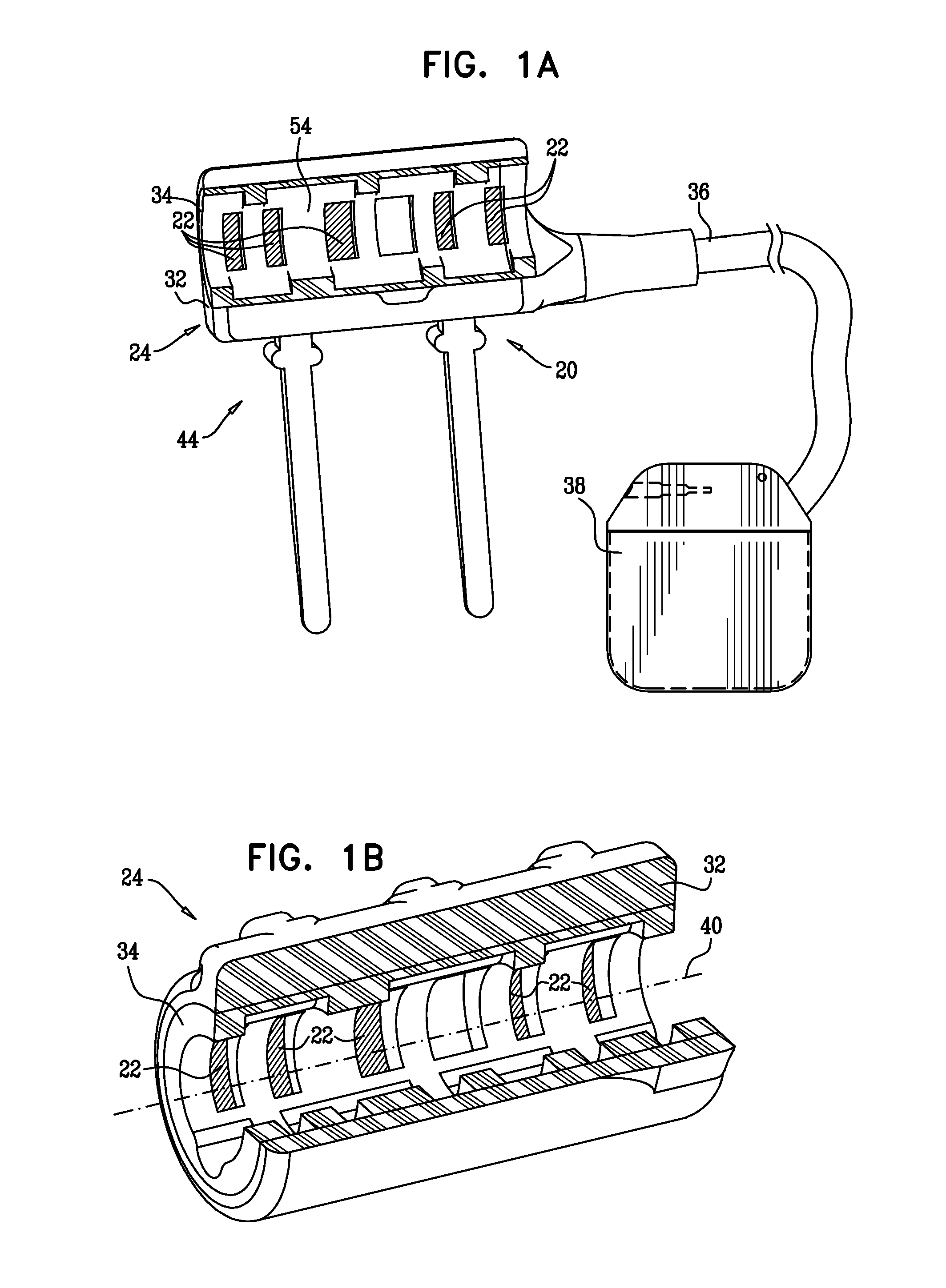
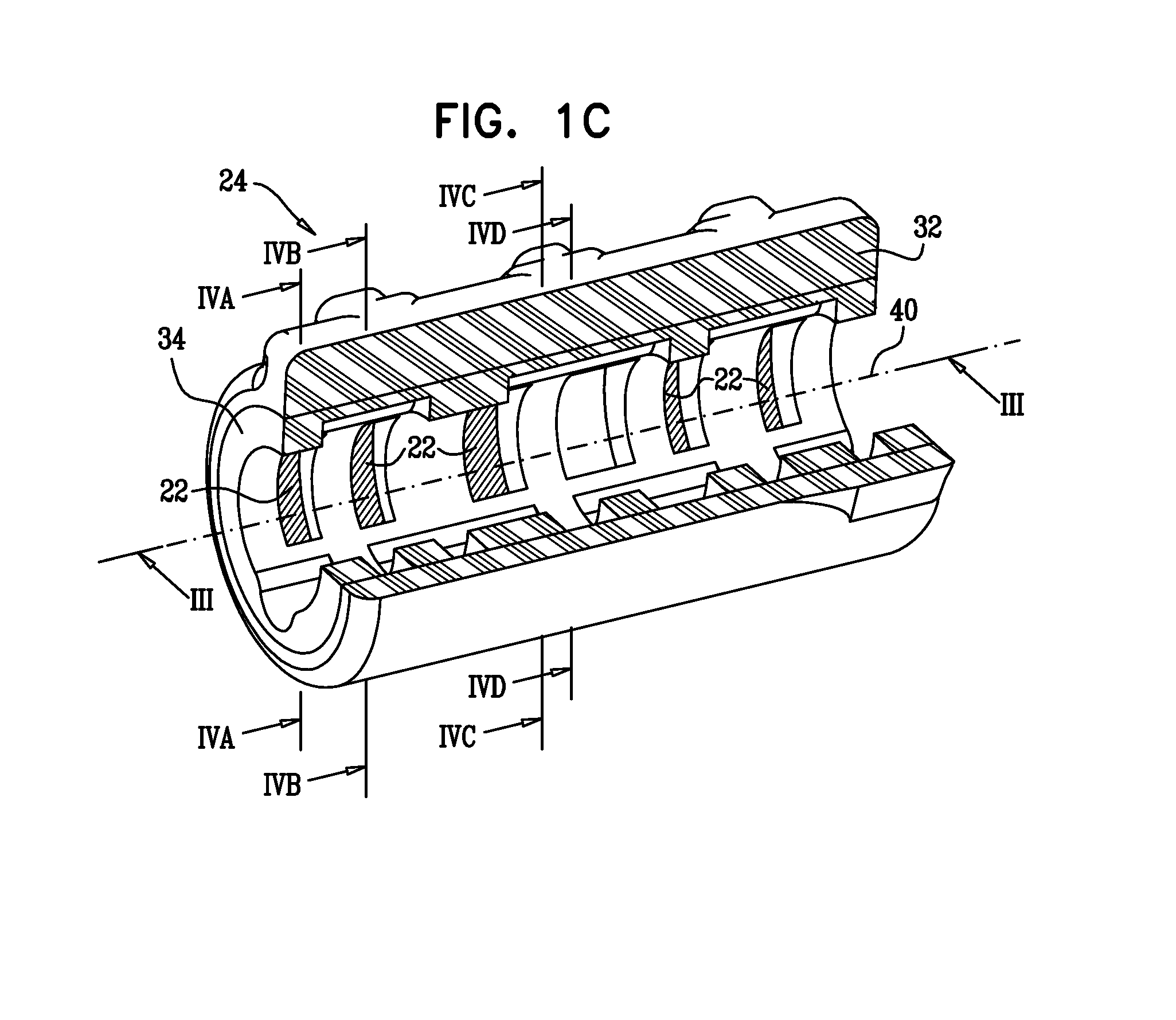
[1258]FIG. 1A is a schematic cut-away illustration of an electrode assembly 20, and FIGS. 1B and 1C are schematic cut-away illustrations of a cuff 24 of electrode assembly 20, in accordance with an embodiment of the present invention. Electrode assembly 20 comprises cuff 24 and one or more electrode contact surfaces 22. Cuff 24 is configured to be placed at least partially around (typically entirely around) a nerve or other tubular body tissue, such as a blood vessel, a muscle, a tendon, a ligament, an esophagus, intestine, a fallopian tube, a neck of a gall bladder, a cystic duct, a hepatic duct, a common hepatic duct, a bile duct, and / or a common bile duct. Cuff 24 defines and at least partially surrounds (typically entirely surrounds) a longitudinal axis 40. The cross section of FIG. 1A shows 180 degrees of a circumference of cuff 24 (i.e., 50% of the cuff; the cuff actually completely surrounds 360 degrees of axis 40), while the cross section of FIG. 1B shows 270 degrees of the ...


PUM


Abstract

An electrode device is configured to be coupled to a parasympathetic site of a subject. A control unit is configured to drive the electrode device to apply a current in bursts of one or more pulses, during “on” periods that alternate with low stimulation periods, wherein at least one of the low stimulation periods immediately following the at least one of the “on” periods has a low stimulation duration equal to at least 50% of the “on” duration; set the current applied on average during the low stimulation periods to be less than 20% of the current applied on average during the “on” periods; and ramp a number of pulses per burst during a commencement of the at least one of the “on” periods and/or a conclusion of the at least one of the “on” periods.

Description

CROSS-REFERENCE TO RELATED APPLICATIONS[0001]The present application is a continuation-in-part of:[0002](a) U.S. patent application Ser. No. 12 / 952,058, filed Nov. 22, 2010;[0003](b) U.S. patent application Ser. No. 12 / 228,630, filed Aug. 13, 2008;[0004](c) U.S. patent application Ser. No. 13 / 022,199, filed Feb. 7, 2011, which is a divisional of U.S. patent application Ser. No. 11 / 517,888, filed Sep. 7, 2006, now U.S. Pat. No. 7,904,176;[0005](d) U.S. patent application Ser. No. 12 / 012,366, filed Feb. 1, 2008, which claims the benefit of (i) U.S. Provisional Application 60 / 937,351, filed Jun. 26, 2007, and (ii) U.S. Provisional Application 60 / 965,731, filed Aug. 21, 2007; and[0006](e) U.S. patent application Ser. No. 13 / 022,279, filed Feb. 7, 2011, which is a continuation-in-part of:[0007](i) U.S. patent application Ser. No. 11 / 234,877, filed Sep. 22, 2005, now U.S. Pat. No. 7,885,709, which claims the benefit of (1) U.S. Provisional Patent Application 60 / 612,428, filed Sep. 23, 200...

Claims


Application Information

Patent Timeline
IPC IPC(8): A61N1/36
CPCA61N1/36139A61N1/36189A61N1/0556A61B5/7285A61B5/1118A61B5/14503A61B5/14546A61N1/36053A61N1/36114A61N1/36178A61N1/3615A61B5/24
Inventor BEN-EZRA, OMRYBEN-DAVID, TAMIRCOHEN, EHUDAYAL, SHAI
Owner MEDTRONIC INC
Why Eureka
Try Eureka