Method and control unit for setting a temperature of a glow plug

a technology of glow plugs and temperature, which is applied in the direction of engine starters, light and heating apparatus, machines/engines, etc., can solve the problems of overshooting of glow plugs and overloaded glow plugs, and achieve the effect of reducing development efforts and increasing measured resistan

Active Publication Date: 2014-02-27
ROBERT BOSCH GMBH
View PDF10 Cites 5 Cited by
  • Summary
  • Abstract
  • Description
  • Claims
  • Application Information

AI Technical Summary

Benefits of technology

[0005]According to the present invention, the object is achieved in that the temperature is controlled in a preheating phase of the glow plug in which an overvoltage is applied to the glow plug. The advantage of the present invention is that the glow temperature is now modulated at high quality over the entire glow process of the glow plug, and the control of the glow temperature takes place at every point in time of the glow phase, advantageously also during the preheating phase (push phase) during which the heater of the glow plug applies an excessively high heating voltage to the cold glow plug during a short time period of 1 to 2 seconds. This makes it possible to better manage the preheating phase during a key start as well as during long starting phases.
[0006]To control the temperature of the glow plug during the preheating phase, a resistance difference, which exists in relation to a measured resistance at the end of the preheating phase, is advantageously anticipatorily determined during the preheating phase with the aid of a physical model. In this way, the temperature is controlled with the aid of the predictive model during the preheating phase during which an overvoltage is applied to the glow plug. In this way, the preheating phase of the glow plug is more robust, since no or only small temperature overshoots occur and exact input values are also made available for the control of the further glow characteristic of the glow plug. Thus, the control is closely adjusted to the desirable temperature setpoint value already during the preheating phase. By determining the resistance difference, the input variable of the resistance is initialized for the control, and the point in time is also taken into account during the initial energization of the glow plug. Furthermore, the development effort is reduced, since an application for a controlled preheating is not necessary and the input parameters are determined only once and are maintained for the lifetime of the glow plug.
[0007]In one embodiment, the measured resistance of the glow plug is added to the resistance difference, and the sum formed from the measured resistance and the resistance difference is supplied to the control. In this way, the measured resistance is increased by an anticipatorily determined absolute value which corresponds to the temperature actually occurring in the glow plug during the preheating phase.
[0008]In one refinement, the resistance difference includes multiple, in particular summed up, partial resistance differences, each partial resistance difference being determined as a function of at least one operating parameter of the glow plug. In this way, the state of the glow plug is characterized at the start of a glow process during the initial energization of the glow plug and optimized by using corresponding characteristic curves.
[0009]In one variant, a first partial resistance difference is determined as a function of an energy content of the glow plug which the glow plug has at the point in time of the start of the glow process. In this way, the initial characteristic of the glow plug at the point in time of the start of the glow process is taken into account for the determination of the resistance difference.
[0010]In particular, the energy content of the glow plug is characterized by an initial resistance, an initial amount of heat, or an initial performance. Thus, the heat balance of the cold glow plug prior to the initial energization is taken into account. Since, for example, the initial resistance of the cold glow plug is very small, while the initial resistance of a glow plug which has already been preheated once is greater, it is ensured that the correct input variable is always used for the determination of the resistance difference.

Problems solved by technology

For this purpose, the glow plug has a heater which applies an excessively high heating voltage to the cold glow plug during a short time period of 1 to 2 seconds, so that the glow plug is overloaded at this point in time.
By activating the glow plug using an excessively high heating voltage, a temperature overshoot is produced on the glow plug.
Since this input variable for the control is, however, ascertained during a transient reaction, this results in errors during the following control.

Method used


Image

  • Method and control unit for setting a temperature of a glow plug
  • Method and control unit for setting a temperature of a glow plug
  • Method and control unit for setting a temperature of a glow plug

Examples


Embodiment Construction

[0021]Cold internal combustion engines, in particular diesel engines, require a starting aid for igniting the fuel / air mixture introduced into the diesel engine in the case of ambient temperatures of <40° C. As the starting aid, glow systems are then used which include glow plugs, a glow control unit, and a glow software which is stored in an engine control unit or in the glow control unit. Moreover, glow systems are also used to improve the emissions of the vehicle. Other areas of application for the glow system are the burner exhaust gas system, the engine block heater, when preheating the fuel (flex fuel) or when preheating the cooling water.

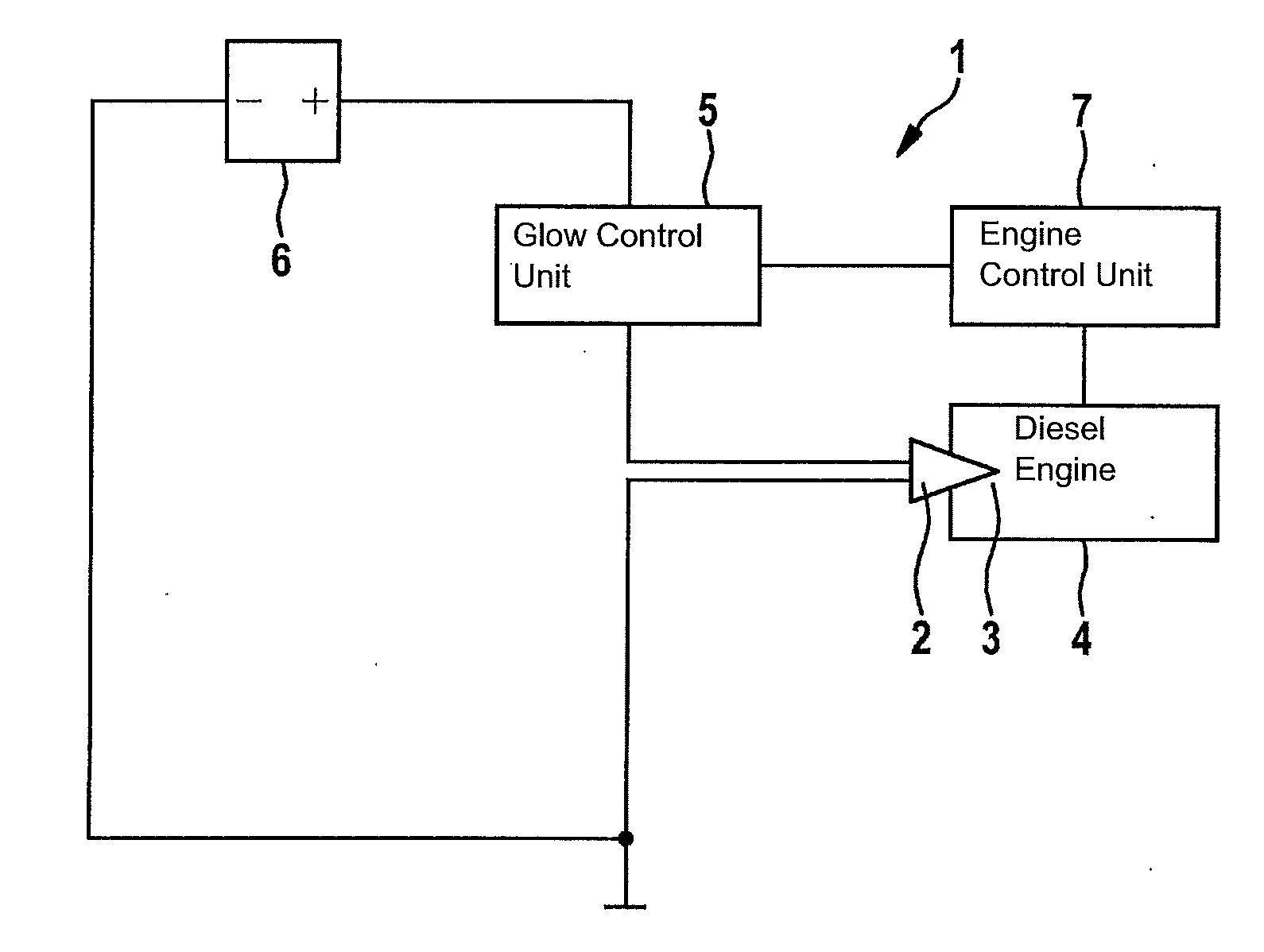
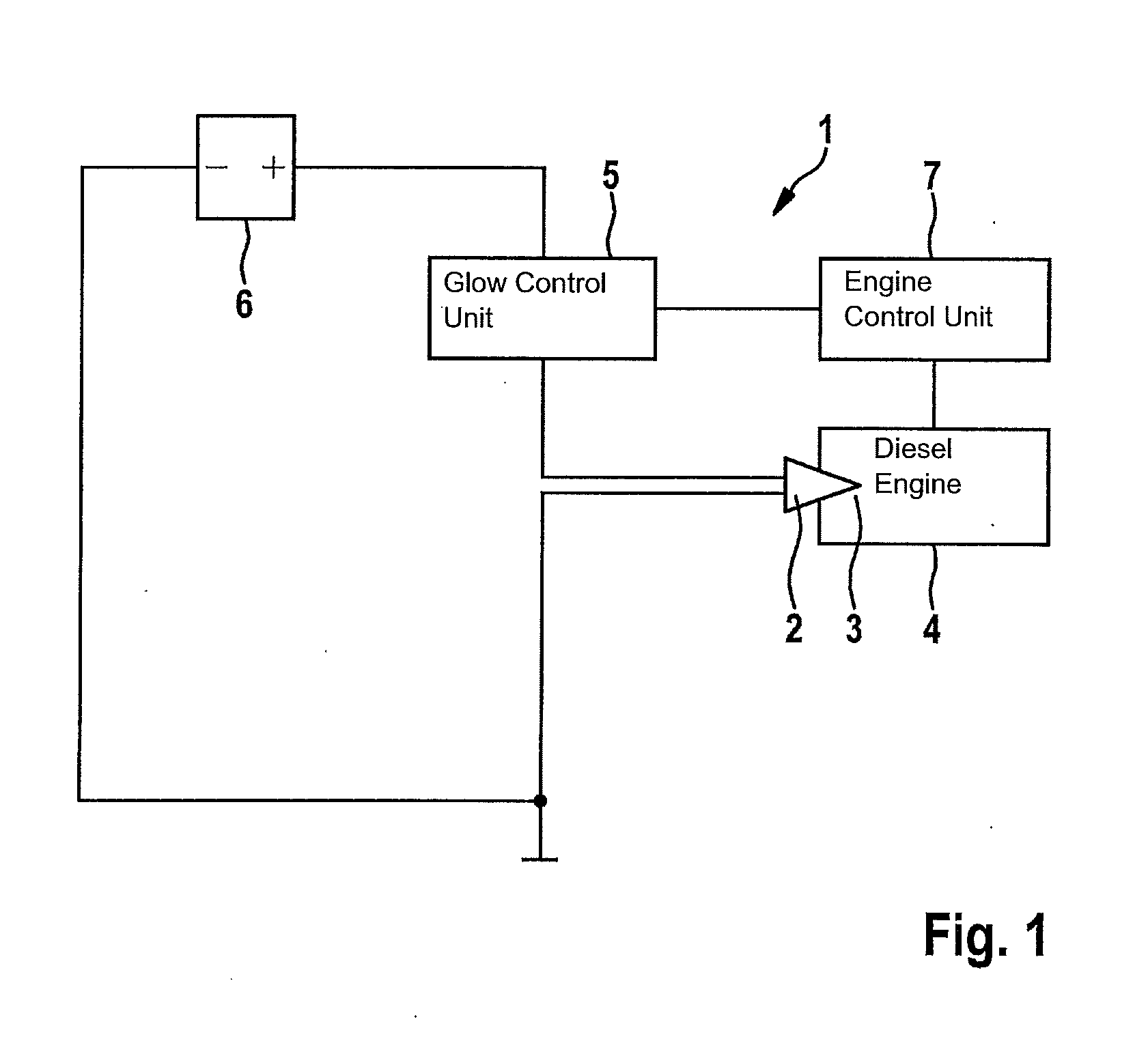
[0022]FIG. 1 shows such a glow system 1. Here, a glow plug 2 protrudes into combustion chamber 3 of diesel engine 4. Glow plug 2 is on the one hand connected to glow control unit 5 and on the other hand leads to a battery 6 which activates glow plug 2 at the nominal voltage of 11 volts, for example. Glow control unit 5 is connected to engine ...


PUM


Abstract

A method is described for setting a temperature of a glow plug, in particular for igniting a fuel / air mixture in an internal combustion engine in which the temperature of the glow plug is set as a function of a resistance of the glow plug with the aid of a control. To prevent temperature overshoots from occurring during the preheating phase of the glow plug, the temperature is controlled with the aid of a predictive model during a preheating phase during which an overvoltage is applied to the glow plug.

Description

FIELD OF THE INVENTION[0001]The present invention relates to a method for setting a temperature of a glow plug, in particular for igniting a fuel / air mixture in an internal combustion engine in which the temperature of the glow plug is set with the aid of a control as a function of a resistance of the glow plug, as well as a control unit for carrying out the method.BACKGROUND INFORMATION[0002]Glow plugs, which are installed in internal combustion engines for igniting a fuel / air mixture, are preheated in the cold state until their temperature is high enough to be sufficient to ignite the fuel / air mixture. For this purpose, the glow plug has a heater which applies an excessively high heating voltage to the cold glow plug during a short time period of 1 to 2 seconds, so that the glow plug is overloaded at this point in time. After completion of this so-called push phase, the tip of the glow plug reaches a temperature of more than 1000° C., while the rest of the glow plug still has a te...

Claims


Application Information

Patent Timeline
Patent Type & Authority Applications(United States)
IPC IPC(8): F02P19/02
CPCF02P19/021F02P19/023F02P19/025
Inventor JOOS, SASCHAJANZEN, EBERHARDRYLL, HARALD
Owner ROBERT BOSCH GMBH
Why Eureka
Try Eureka