Rotational clap suction/pressure device

a technology of suction device and clap, which is applied in the direction of machines/engines, rotary/oscillating piston pump components, liquid fuel engines, etc., can solve the problems of very restrictive use of rotary engines of wankel sports cars, improve and improve the coupling strength of crank arms. , the effect of improving the mechanical strength of rotational pistons

Inactive Publication Date: 2014-02-27
KIM JONG MUN
View PDF5 Cites 19 Cited by
  • Summary
  • Abstract
  • Description
  • Claims
  • Application Information

AI Technical Summary

Benefits of technology

[0043]As described above, according to the present invention, the power transmission elements for operating the pistons may be disposed within a gear box outside the cylindrical housing to improve the mechanical strength of the rotational pistons and to superiorly cope with the high-temperature high-pressure environment in the fluid.
[0044]Also, according to the present invention, the crank arm may be integrated with the crankshaft, but not integrated with the cylinder, to increase the coupling strength of the crank arm. Also, the one rotational piston may be dispersed into the two rotation pins to operate, thereby improving the power transmission efficiency and the mechanical strength.
[0045]Also, according to the present invention, the non-uniformly rotated two rotational pistons may be combined with each other to change the volume of the chamber, thereby suctioning and compressing the fluid. In addition, the housing and the rotational pistons may completely surface-contact each other to significantly reduce the abrasion and improve the durability and efficiency.
[0046]Also, in the typical vacuum pump, although the vane pump, piston type pump, and water seal type (a centrifugal type) pump are widely used as the vacuum pump, the pump should be more complicated and increased in processing accuracy so as to increase a degree of vacuum. However, according to the present invention, the various pumps may be replaced to effectively realize the degree of vacuum with a more simplified structure and small size.
[0047]Also, according to the present invention, various gas compressors may be small-sized and lightweight to perform a function of a high-pressure positive displacement compressor by using a compressor having a simplified structure such as the vane type compressor. Thus, the present invention may provide a new positive displacement blower having a significant small size and simplified structure as a blower which is capable of replacing the representative positive displacement roots blower to generate the same amount and pressure of wind.
[0048]Also, the present invention has advantages such as the simplified structure and sealing maintenance in flow meter properties. Thus, the flow meter according to the present invention may replace the gear type flow meter, the piston type flow meter, and the diaphragm type flow meter which are widely used as the existing positive displacement flow meter to provide a small-sized structure in which a loss of a pressure is reduced, and measuring accuracy is improved.

Problems solved by technology

The Wankel rotary engine is very restrictively used in some sports cars.

Method used


Image

  • Rotational clap suction/pressure device
  • Rotational clap suction/pressure device
  • Rotational clap suction/pressure device

Examples


first embodiment

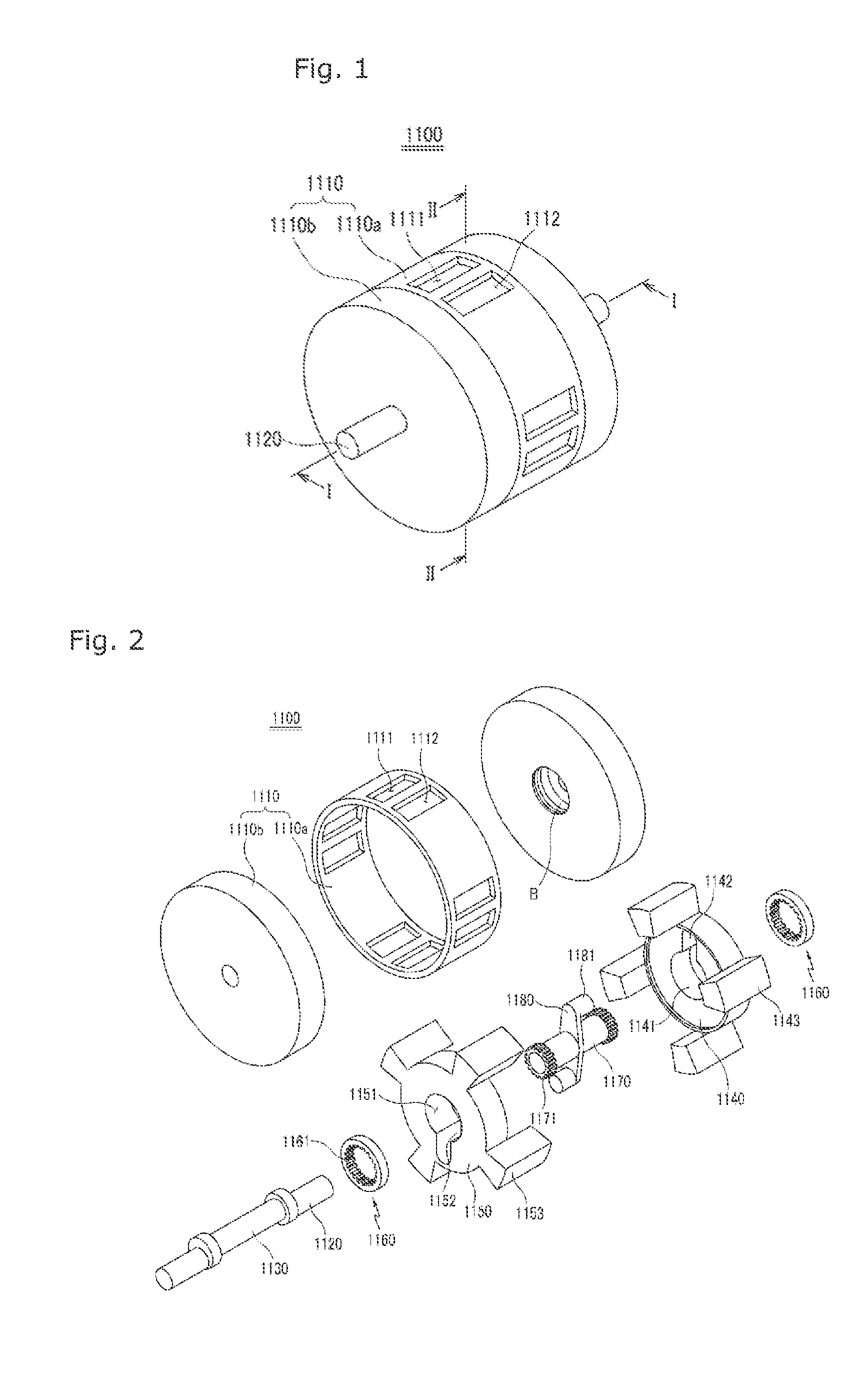
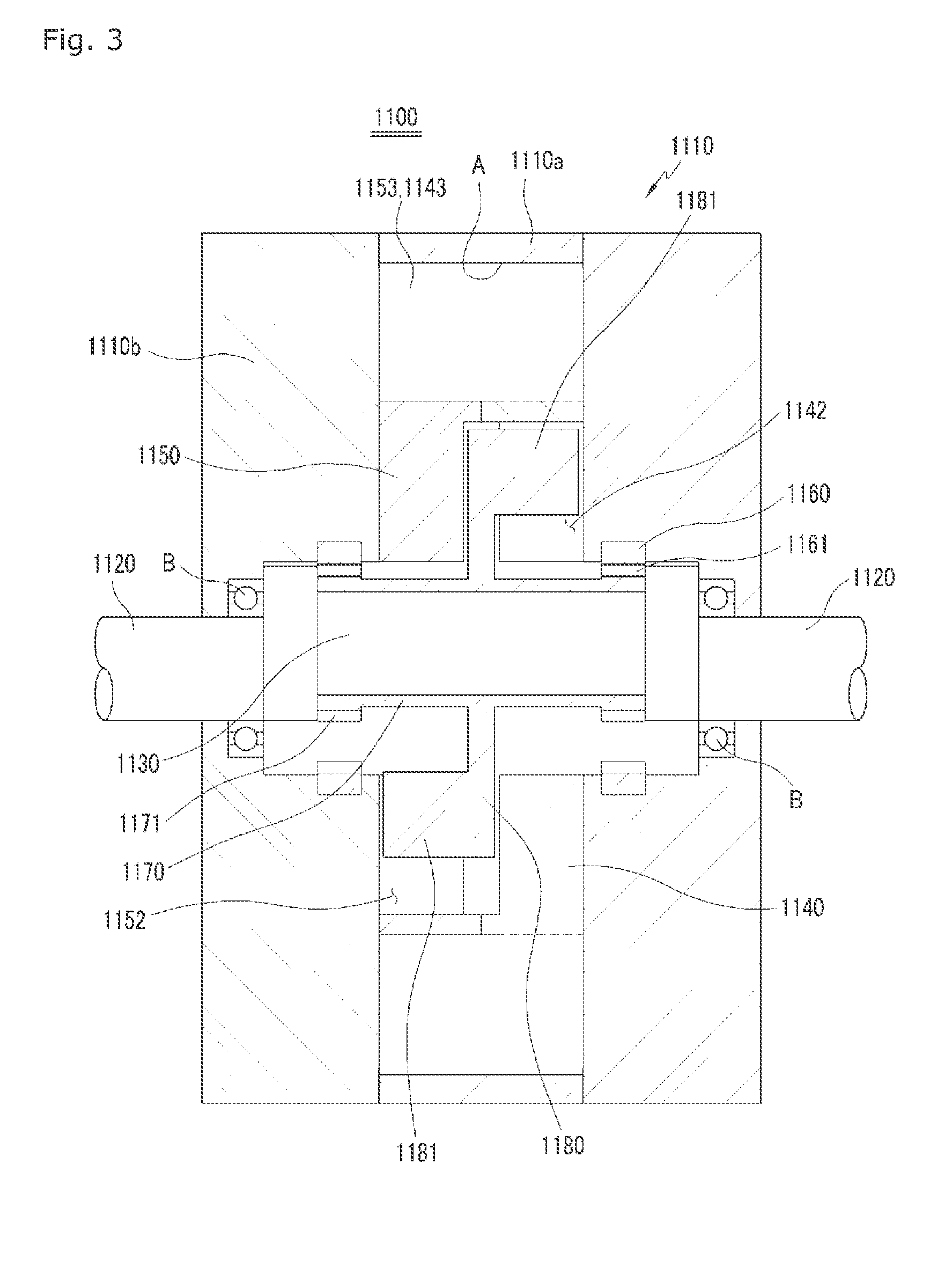
[0104]A rotational clap suction / pressure device 1100 according to a first embodiment of the present invention, in which four blades 1143 and 1153 are disposed on each of first and second rotational pistons 1140 and 1150, will be described.

[0105]Referring to FIGS. 1 to 8, a rotational clap suction / pressure device 1100 according to a first embodiment includes: a cylindrical housing 1110 in which four suction holes 1111 and discharge holes 1112 are defined in a housing cylinder 1110a at a predetermined distance, and a housing side plate 1110b is disposed on each of both sides of the housing cylinder 1110a; a crankshaft 1120 configured to operate a central portion of the housing side plate 1110b, the crankshaft 1120 being rotatably supported by the cylindrical housing 1110; a crankpin 1130 that is eccentric to the crankshaft 1120 to extend from a central portion of the crankshaft 1120; a first rotational piston 1140 rotatably disposed within the cylindrical housing 1110, the first rotat...

second embodiment

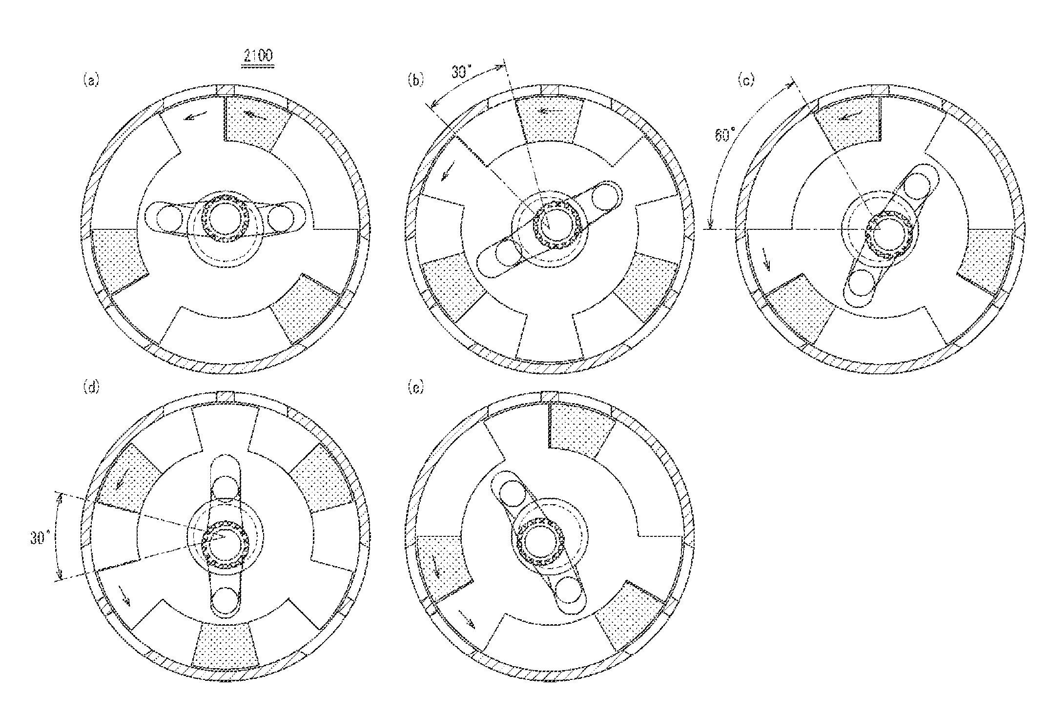
[0117]A rotational clap suction / pressure device 2100 according to a second embodiment of the present invention will be described.

[0118]A rotational clap suction / pressure device 2100 according to the second embodiment of the present invention, in which three blades 1143 and 1153 are disposed on each of first and second rotational pistons 1140 and 1150, will be described. Here, since the rotational clap suction / pressure device 2100 according to the second embodiment of the present invention has the same constitution as the above-described rotational clap suction / pressure device 1100 according to the first embodiment of the present invention except for the number of blades, for convenience of description, the same component is denoted by the same reference numeral.

[0119]Referring to FIGS. 10A to 10E, when the number of each of blades 1143 and 1153 is three, a fixed internal gear 1161 and a planetary external gear 1171 is set to a gear ratio of about 3:2.

[0120]When a crankshaft 1120 is ...

third embodiment

[0122]A rotational clap suction / pressure device 3100 according to a third embodiment of the present invention, in which two blades 1143 and 1153 are disposed on each of first and second rotational pistons 1140 and 1150, will be described. Here, since the rotational clap suction / pressure device 3100 according to the third embodiment of the present invention has the same constitution as the above-described rotational clap suction / pressure device 1100 according to the first embodiment of the present invention except for the number of blades, for convenience of description, the same component is denoted by the same reference numeral.

[0123]Referring to FIGS. 11A to 11E, when the number of each of blades 1143 and 1153 is two, a fixed internal gear 1161 and a planetary external gear 1171 is set to a gear ratio of about 3:2.

[0124]When a crankshaft 1120 is non-uniformly rotated in a clockwise direction by a motor (not shown) that is a power source, a rotation pin 1181 of a connecting rod 118...


PUM


Abstract

The present invention relates to a simple and straightforward positive displacement suction / pressure device (rotational clap suction / pressure device) for utilizing in general industrial flow machines, such as various positive displacement pumps, vacuum pumps, compressors, flow meters, and rotary internal combustion engines. The object of the present invention using a double non-uniform rotation is to provide a simple and durable mechanical device having improved efficiency, by replacing the existing linear contact between various types of rotors or between a rotor and a housing, which is a problem in existing positive displacement flow machines and rotary internal combustion engines, with a whole surface.

Description

TECHNICAL FIELD[0001]The present invention relates to a positive displacement suction / pressure device that is utilized in overall industrial fluid machines such as various positive displacement peristaltic pumps, vacuum pumps, gas compressors, positive displacement air blowers, gas and liquid flow meters, or rotary internal combustion engines, and more particularly, to a positive displacement suction / pressure device (hereinafter, referred to as a “rotational clap suction / pressure device”) in which two rotational piston blades are rotated in the same direction as if a person clap his hands so that a change in volume between the blades is used for suctioning a fluid.BACKGROUND ART[0002]Recently, a vane pump and a gear pump which have relatively simple structures and a piston and plunger type pump and a screw pump which are relatively complicated and have relatively large scales are widely used as positive displacement liquid transfer pumps.[0003]In general vacuum pumps, a vane pump, a...

Claims


Application Information

Patent Timeline
Patent Type & Authority Applications(United States)
IPC IPC(8): F04C18/08
CPCF04C18/08F04C2/077F04C15/0061F01C1/077
Inventor KIM, JONG-MUN
Owner KIM JONG MUN
Why Eureka
Try Eureka