Non ionic groups of amphoteric polysaccharide linear or branched alkyl or acid and base distillation reservoir liquid or gas mechanically refined and Nano particle dispersion and recovery basin in vacuum processing for Building Materials and High Wear-Heat Resistant Parts Brushes; Windings; Coils; Battery Cells; Brake Pads; Bushings; 2.5 Phase Extrusions Die Cast Molding; Refrigeration; Polarized Glass; and Central Processing Unit Processors.

a technology of nano particles and amphoteric polysaccharides, which is applied in the direction of printing, textiles and papermaking, industrial buildings, etc., can solve the problems of improving the technological structure of carbon nanofoam cnfs collection and manufacturing, and achieve the effect of high wear resistan

Inactive Publication Date: 2014-02-27
MATTHEWS ROBERT RICHARD
View PDF3 Cites 31 Cited by
  • Summary
  • Abstract
  • Description
  • Claims
  • Application Information

AI Technical Summary

Benefits of technology

[0005]Scientific utilization of preform technology the Variable hydraulic preform slurry non ionic or electrolyte carbon nanofoam CNFs extrusion high wear-heat resistant parts press FIG. 1 with manufactured or processed carbon nanofoam CNFs available resources enables the manufacture process of high wear-heat resistant parts electronic component composite coils, composite windings, drawn, annealing, spun, coils, windings, wire, woven textile mesh, shielding, brushes, inductors, antinode couplers, electric rheostats, starters, motors, alternators, generators, ionic suspension element enhanced composite coils, composite windings, drawn, annealing, spun, coils, windings, wire, wove

Problems solved by technology

Few technological developments of collecting and manufacturing carb

Method used


Image

  • Non ionic groups of amphoteric polysaccharide linear or branched alkyl or acid and base distillation reservoir liquid or gas mechanically refined and Nano particle dispersion and recovery basin in vacuum processing for Building Materials and High Wear-Heat Resistant Parts Brushes; Windings; Coils; Battery Cells; Brake Pads; Bushings; 2.5 Phase Extrusions Die Cast Molding; Refrigeration; Polarized Glass; and Central Processing Unit Processors.
  • Non ionic groups of amphoteric polysaccharide linear or branched alkyl or acid and base distillation reservoir liquid or gas mechanically refined and Nano particle dispersion and recovery basin in vacuum processing for Building Materials and High Wear-Heat Resistant Parts Brushes; Windings; Coils; Battery Cells; Brake Pads; Bushings; 2.5 Phase Extrusions Die Cast Molding; Refrigeration; Polarized Glass; and Central Processing Unit Processors.

Examples


Embodiment Construction

. 1

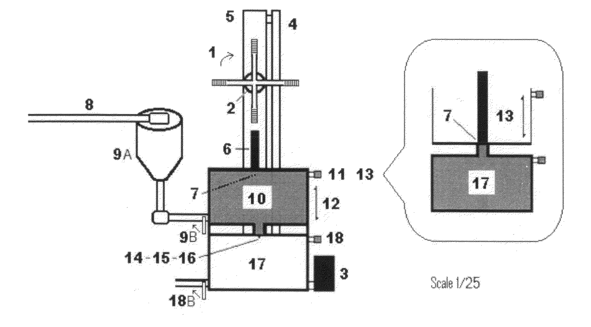
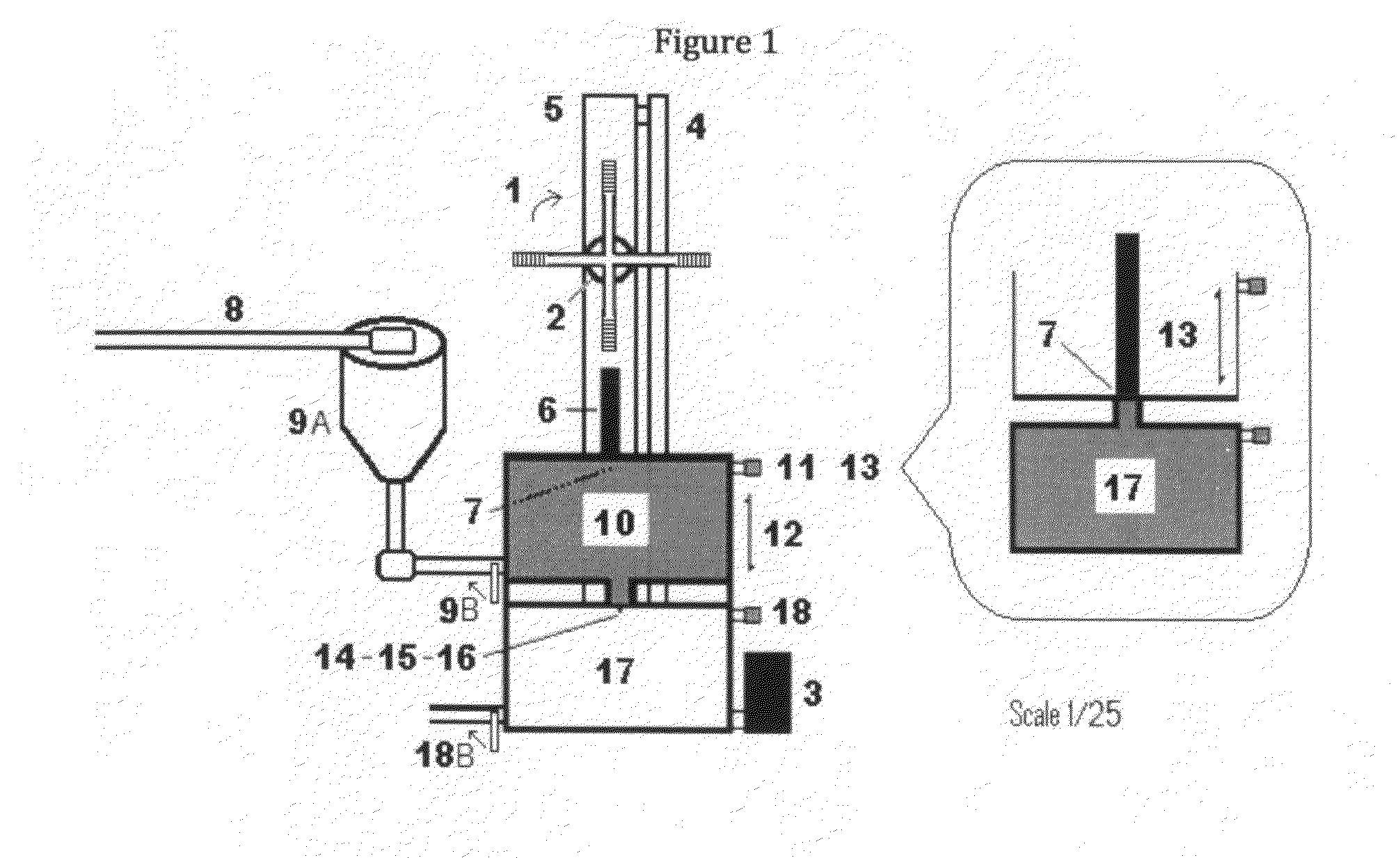
[0004]Variable hydraulic preform slurry non ionic or electrolyte carbon extrusion high wear-heat resistant parts press 1-Hydraulic control wheel 2-Electronic servo 3-Hydraulic pump 4 Hydraulic pipe 5—Hydraulic actuator 6—Hydraulic tool steel arm 7—Slurry carbon tool steel press plate 8—Slurry carbon tool steel line in 9A—Gravity feed tool steel collector 9B—Tool steel release portal control 10—Slurry carbon tool steel reservoir 11—Slurry carbon reservoir regulated tool steel waste filter 12—Slurry carbon tool steel reservoir expanded 13—Slurry carbon tool steel reservoir contracted 14—Slurry carbon reservoir brass—tool steel aperture 15—Tool steel extrusion die cast design brass—tool steel fitting 16—Tool steel electronic servo or manual stop control release pull pin 17—Tool steel extrusion die cast design internal cavity 18—Tool steel extrusion die cast design internal cavity regulator waste filter and 18B—Tool steel vacuum release portal control.

BRIEF SUMMARY OF THE INVENTION

[0...


PUM

PropertyMeasurementUnit
Temperatureaaaaaaaaaa

Abstract

Manufacture process scientific formula mechanically refined and nanoparticle dispersion preform slurry non ionic or electrolyte carbon nanofoam CNFs with or without ionic suspension elements manufactured, Preform slurry high wear-heat resistant parts electronic component composite coils, composite windings, drawn, annealing, spun, coils, windings, wire, woven textile mesh, shielding, brushes, inductors, antinode couplers, electric rheostats, starters, motors, alternators, generators, ionic suspension element enhanced composite coils, composite windings, drawn, annealing, spun, coils, windings, wire, woven textile mesh, shielding, brushes, capacitors, battery cells, rheostats, electronic resistors, transformers, transducers, rectifiers, power supplies, or heat sinks, Preform slurry carbon nanofoam CNFs extrusion high wear-heat resistant parts aerospace, automotive, and transportation brake calipers, rotors, pads, washers, spacers, and bushings, Preform slurry carbon nanofoam CNFs extrusion high wear-heat resistant parts precision casting molds manufacturing highly pure metal, Super Alloy, acid-solid, alkaline, glass, acrylic, halide, alkalide, or ceramics specializing in 2.5 phase die cast molding.

Description

DOMESTIC PRIORITY DATA[0001]This is an application a continuation in part of preliminary amendment to specification Application-number 13595610 Filing Date Aug. 27, 2012.BACKGROUND OF THE INVENTION[0002]Global warming and growing concerns of Greenhouse gas emissions from our dependency on fossil fuels are creating real demand and awareness for an electric alternative to gasoline engines and expensive replacement parts. Few technological developments of collecting and manufacturing carbon nanofoam CNFs improve upon our existing technological structure. By applying scientific utilization of preform technology the Variable hydraulic preform slurry non ionic or electrolyte carbon nanofoam CNFs extrusion high wear-heat resistant parts press with manufactured or processed carbon nanofoam CNFs assembled resources we can now create the manufacture process of Preform slurry non ionic or electrolyte carbon nanofoam CNFs extrusion high wear-heat resistant parts.BRIEF DESCRIPTION OF FIG. 1[0003...

Claims


Application Information

Patent Timeline
IPC IPC(8): B28B7/00B30B15/00B22D15/00E04H5/02B29C33/38
CPCB28B7/00E04H5/02B30B15/00B22D15/00B29C33/38C04B35/52C04B38/0054B22D17/22Y10T442/102
Inventor MATTHEWS, ROBERT RICHARD
Owner MATTHEWS ROBERT RICHARD
Why Eureka
Try Eureka