
Mixer having frequency selectivity

a frequency selectivity and mixer technology, applied in the field of mixers, can solve the problems of not meeting the requirements of a tunable filter, existing oscillation resonators, and saturated frequency bands allocated to wireless communication, and achieve the effects of high multiplication signal, improved frequency selectivity of band-pass filter functions, and enhanced resonance characteristics

Active Publication Date: 2014-02-27
TDK CORPARATION
View PDF6 Cites 6 Cited by
  • Summary
  • Abstract
  • Description
  • Claims
  • Application Information

AI Technical Summary

Benefits of technology

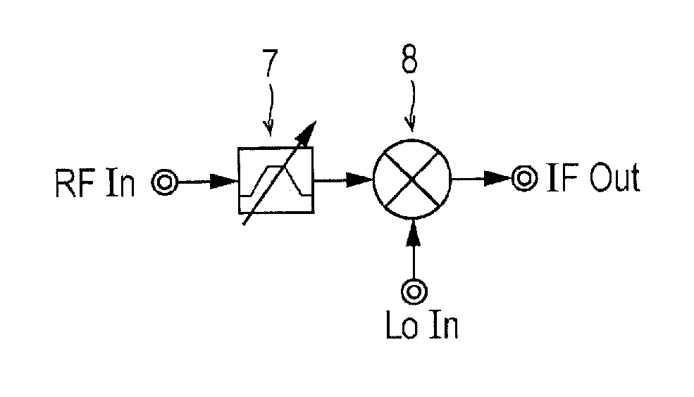
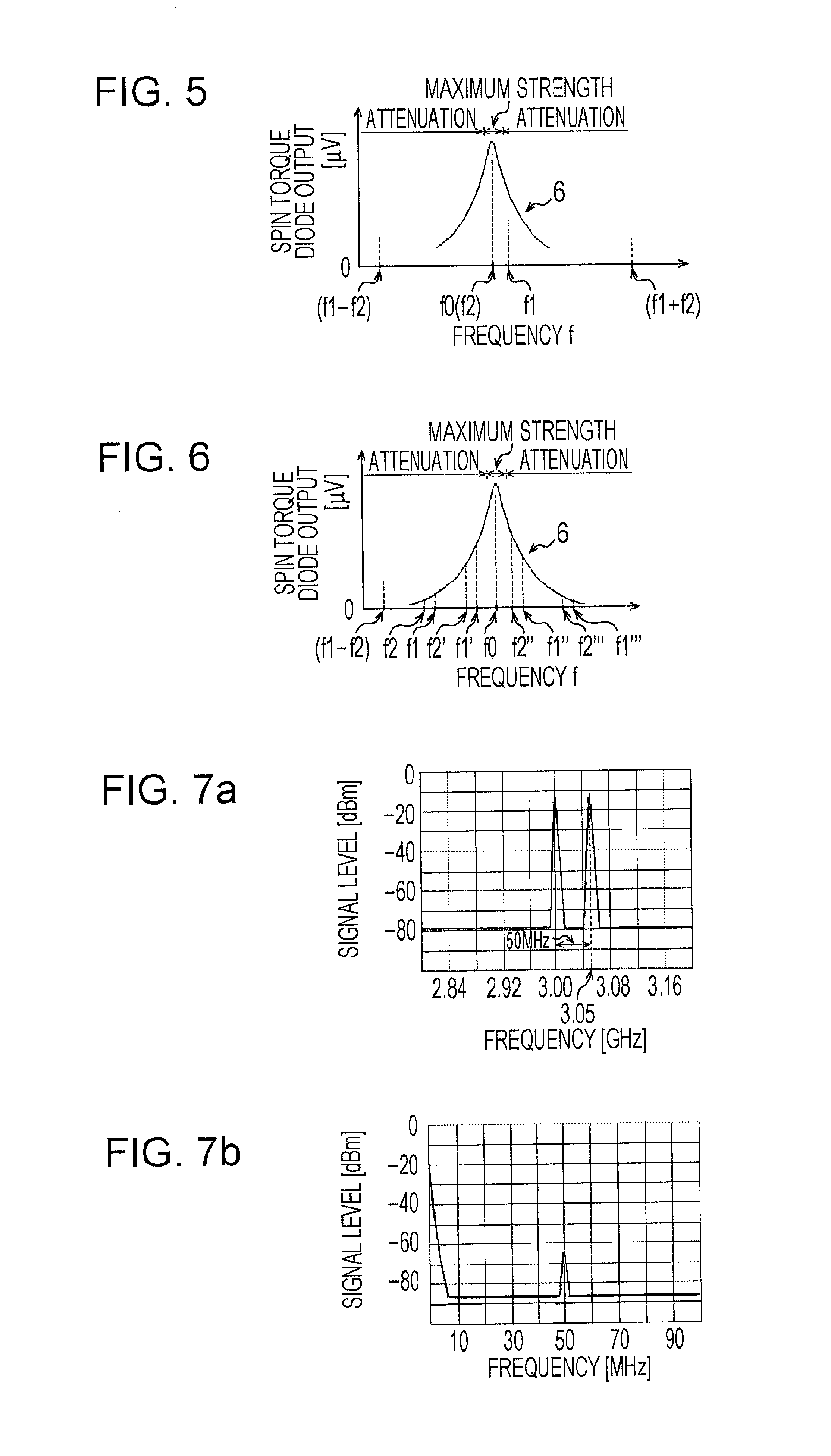
The present invention solves the problem of reducing the output of a multiplication signal in a mixer while maintaining a high-quality signal. The invention provides a mixer with a frequency selective attenuator function through the use of resonance characteristics with a Q factor of 100 or higher. The invention also utilizes a magnetic field applying unit to improve the resonance characteristics of the magnetoresistance effect element, resulting in a narrower attenuation curve of the multiplication signal and better band-pass filter function. The impedance circuit of the invention ensures high impedance in the frequency band of the multiplication signal to prevent a decrease in signal power. The mixer of the invention achieves power savings and improved band-pass filter function.

Problems solved by technology

These days, frequency bands allocated to wireless communication are becoming saturated.
At present, existing oscillation resonators, such as SAW (Surface Acoustic Wave: surface acoustic wave element, and more specifically, a filter element utilizing surface acoustic waves propagating on the surface of a piezoelectric body) and BAW (Bulk Acoustic Wave: a filter element utilizing resonant oscillation of a piezoelectric film itself called bulk acoustic waves) do not satisfy such requirements for a tunable filter.
On the other hand, however, a compact tunable band-pass filter which can be fit in a portable terminal has not yet been realized.
Although the characteristics of a mixer using the above-described magnetoresistance effect element are known, a high frequency device that can apply such characteristics to an industrial use is still unknown.
However, a high Q factor has not been obtained, and the frequency selection range is too wide, and thus, the applicant of this application has not yet found the application of the above-described characteristics to an industrial use.

Method used


Image

  • Mixer having frequency selectivity
  • Mixer having frequency selectivity
  • Mixer having frequency selectivity

Examples


Embodiment Construction

[0047]An embodiment of a mixer and a frequency converter will be described below with reference to the drawings.

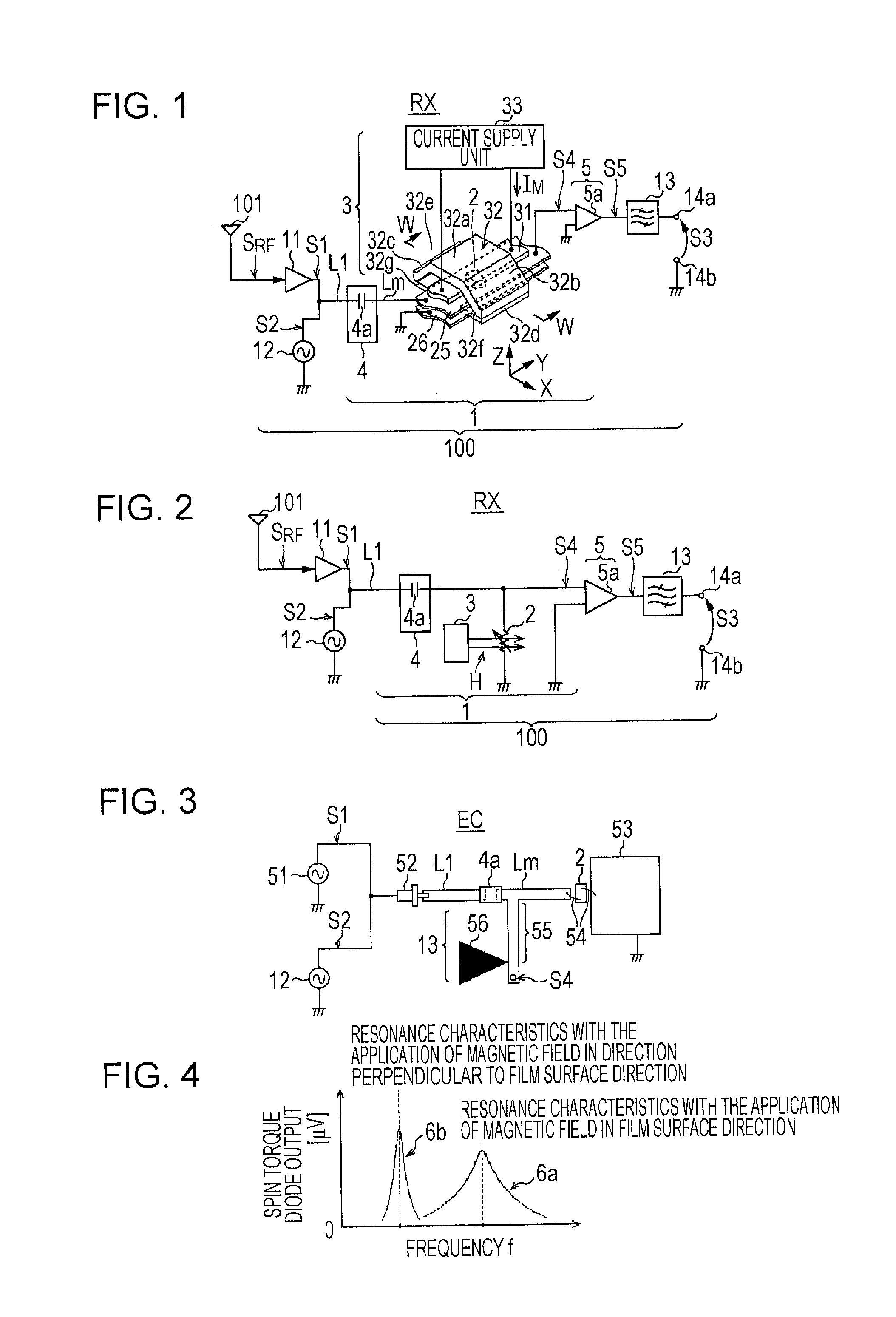
[0048]First, the configuration of a mixer 1 and the configuration of a frequency converter 100 including the mixer 1 will be described below with reference to the drawings. An example in which the frequency converter 100 is applied to a receiver RX will be discussed here.

[0049]The frequency converter 100 shown in FIG. 1 forms the receiver RX together with an antenna 101. The frequency converter 100 is disposed at a radio frequency stage of the receiver RX which receives an RF signal SRF output from the antenna 101, and has a function of converting a frequency f1 of the RF signal SRF into a desired frequency of a multiplication signal S3. In one example, the frequency converter 100 includes the mixer 1, an amplifier 11, a signal generator 12, a filter 13, and output terminals 14a and 14b (hereafter also be referred to as an “output terminal 14” if it is not necessary to dis...


PUM


Abstract

In order to provide a mixer capable of extracting a high multiplication signal and which has a reception band-pass filter function, a magnetoresistance effect element is provided that includes a pinned magnetization layer, a free magnetization layer, and a non-magnetic spacer layer disposed between the pinned magnetization layer and the free magnetization layer. This allows for a frequency converter which implements a desired band-pass filter by controlling a magnetic field applied by a magnetic-field applying unit to be provided.

Description

TECHNICAL FIELD[0001]The present invention relates to a mixer for generating multiplication signals by using a magnetoresistance effect element.BACKGROUND ART[0002]These days, frequency bands allocated to wireless communication are becoming saturated. As measures to deal with this situation, dynamic access concept, which is referred to as “radio opportunistic system (radio-opportunistic)” or “cognitive communication”, is being studied. The principle of this concept is to analyze a frequency spectrum, to avoid a busy occupied frequency bandwidth, to identify and determine an available non-occupied frequency bandwidth, and to change the communication method. However, in order to implement this dynamic frequency access, an ultra-wideband oscillator and a tunable filter are required.[0003]Generally, the reception performance (sensitivity and selectivity) of portable terminals is dependent on a frequency selective attenuator having frequency selectivity (band-pass filter) and a mixer. In...

Claims


Application Information

Patent Timeline
Patent Type & Authority Applications(United States)
IPC IPC(8): H03H7/01
CPCH03H7/0184H03D7/00H10N50/10
Inventor KAKINUMA, YUJITAKAHASHI
Owner TDK CORPARATION
Learn More