Laser engraving devcie

a laser engraving and laser processing technology, applied in metal-working equipment, welding equipment, manufacturing tools, etc., can solve the problems of inconvenient mass production, limited processing range, and disadvantageous effects of laser processing, so as to improve laser processing efficiency, enhance treatment accuracy, and expand the utility range of laser processing

Inactive Publication Date: 2014-03-06
LEGEND LASER
View PDF1 Cites 9 Cited by
  • Summary
  • Abstract
  • Description
  • Claims
  • Application Information

AI Technical Summary

Benefits of technology

[0007]An object of the invention is to provide a laser engraving device which can improve the efficiency of the laser processing, enhance treatment accuracy and expand the utility range of the laser processing.
[0008]To accomplish the above object, the laser engraving device of the invention includes a laser machine for supplying laser beam, a guide rod adjacent to and parallel to the laser machine, a galvanometric scanner coupled to the guide rod and being movable with the guide rod, and a driver disposed at an end of the guide rod for driving the guide rod. When the treatment range exceeds the treatment area of the galvanometer scanner, the galvanometer scanner can be moved to another treatment area to continue treating. This can save the cost of buying a composite lens and solve the abovementioned problem of treatment accuracy.

Problems solved by technology

Thus, it is not suitable for mass production.
However, when the workpiece 12 is too heavy or large to be moved, the efficiency and quality of the laser processing must be disadvantageously affected.
But such an approach makes the processing range and the smallest size of laser spot is limited by the focusing lens of the galvanometer.
The advantages of the latter are a small-sized guiding system, fast treatment and high accuracy, but its drawback is that the treatment area is limited to the composite lens 15 under the galvanometers 13, 14.
This will reduce treatment accuracy and increase the buying cost of the composite lens 15.

Method used


Image

  • Laser engraving devcie
  • Laser engraving devcie
  • Laser engraving devcie

Examples


first embodiment

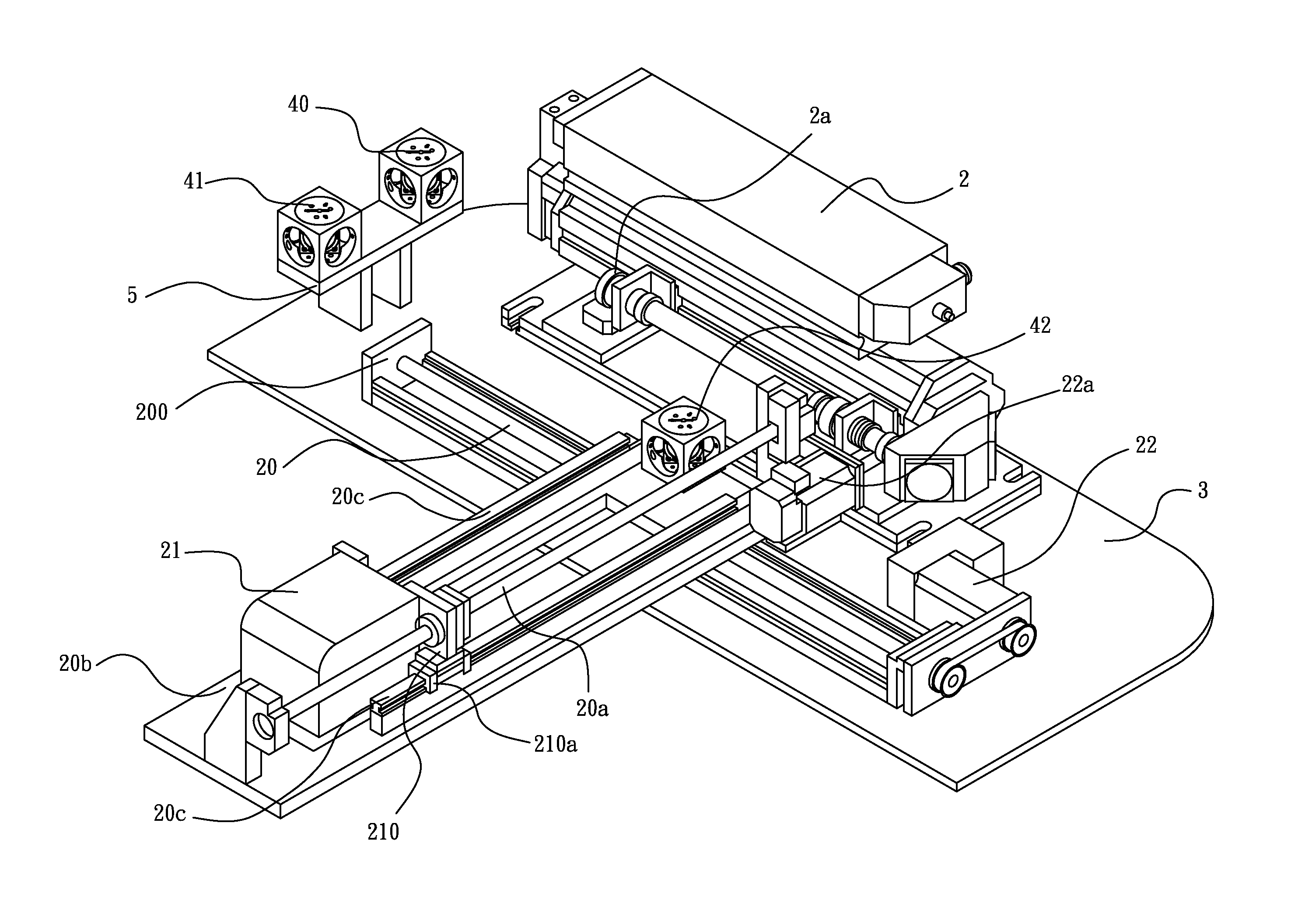
[0015]Please refer to FIG. 3, which show the The laser engraving device of the invention includes a laser machine 2, a first guide rod 20, a galvanometer scanner 21 and a first driver 22.

[0016]The laser machine 2 is used to supply laser beam to the galvanometer scanner 21. The bottom of the laser machine 2 is fixed to a mount 3.

[0017]The first guide rod 20, such as a ball screw, is mounted on a base 200 and adjacently and parallelly disposed beside the laser machine 2.

[0018]The galvanometer scanner 21 makes the received laser beam yaw to different positions by rotation of the internal galvanometer and focuses the received laser beam on the workpiece to scan and engrave. A seat 210 is coupled on the first guide rod 20 to fasten the galvanometer scanner 21 so that the galvanometer scanner 21 can be moved with the first guide rod 20.

[0019]The first driver 22, for example a servo motor, is disposed at an end of the first guide rod 20 for driving the first guide rod 20.

[0020]A plurality...

second embodiment

[0022]To expand the laser treatment range, the invention adds a second guide rod 20a and a second guide rod seat 20b as shown in FIGS. 4 and 5. The second guide rod 20a positions on the second guide rod seat 20b and the second guide rod seat 20b is perpendicularly coupled to the first guide rod 20 for being movable with the first guide rod 20. A second driver 22a is connected to an end of the second guide rod 20a for driving the second guide rod 20a. The galvanometer scanner 21 is coupled to the second guide rod 20a through the seat 210 for being movable with the second guide rod 20a. Preferably, each side of the second guide rod seat 20b is provided with a rail 20c, and the bottom of the seat 210 is formed with a trough 210a corresponding to the rail 20c. The trough 210a abuts against the trough 20c for assisting the seat 210 to move on the second guide rod 20a and then stabilizing the movement of the galvanometer scanner 21. As shown in FIG. 6, the X-Y axes-based movement formed b...


PUM

PropertyMeasurementUnit
areaaaaaaaaaaa
sizeaaaaaaaaaa
weightaaaaaaaaaa

Abstract

A laser engraving device which can adjust its machining position is disclosed. The device includes a laser machine for supplying laser beam, a guide rod adjacent to and parallel to the laser machine, a galvanometric scanner coupled to the guide rod and being movable with the guide rod, and a driver disposed at an end of the guide rod for driving the guide rod.

Description

BACKGROUND OF THE INVENTION[0001]1. Technical Field[0002]The invention relates to laser engraving, particularly to engraving with galvanometers in a large area.[0003]2. Related Art[0004]Laser processing technology has applied in industry for over several decades, for example, applications of welding and cutting. Particularly in the recent years, compact industrial laser becomes popular due to the progress of laser beam sources, a laser engraving device primarily using Nd-YAG laser (i.e. Laser-Marking) is commonly used in metal processing, hand tools, plastic products, electronic components, ceramics, electroplated goods and various gifts.[0005]A general laser processing technique can be divided into two types, which are shown in FIGS. 1 and 2. As shown in FIG. 1, a laser source 10 is fixed at a fixed position. A workpiece 12 is moved by an X-Y carrier 11 and its moving path is controlled by a laser beam, so that the workpiece 12 can be engraved by the laser source 10. FIG. 2 shows t...

Claims


Application Information

Patent Timeline
Patent Type & Authority Applications(United States)
IPC IPC(8): B23K26/08B23K26/36
CPCB23K26/082B23K26/361B23K26/355B23K26/08
Inventor KUO, SHYR-CHERNG
Owner LEGEND LASER
Why Eureka
Try Eureka