Hydraulic tidal and wind turbines with hydraulic accumulator

a technology of hydraulic accumulator and wind turbine, which is applied in the direction of electric generator control, machines/engines, mechanical equipment, etc., can solve the problems of grid inability to tolerate only a limited amount of unscheduled electricity, the unpredictability of wind turbine production can have a negative effect on production schedule, and the time and amount of electrical production of wind turbines are unpredictabl

Inactive Publication Date: 2014-03-06
CARR FRED K
View PDF4 Cites 34 Cited by
  • Summary
  • Abstract
  • Description
  • Claims
  • Application Information

AI Technical Summary

Benefits of technology

[0023]The present invention relates to an electrical power generating system, and methods thereof, for generating electricity from a kinetic energy fuel source as moving water or wind. The generating system is positioned parallel to the fuel source, and rotor blades convert the kinetic energy into mechanical energy. The mechanical energy is transferred to a low-speed hydraulic pump through a rotor shaft, where the pump is driven at rotor speed converting the mechanical energy into hydraulic (fluid) energy which is pumped into a high pressure manifold. The high pressure manifold is coupled to a hydraulic accumulator for storing the fluid energy. The fluid energy is transferred to a high-speed hydraulic motor which converts the fluid energy into mechanical rotation energy which spins a generator coupled to the hydraulic motor. The depressurized fluid is collected in a reservoir to be recycled to the pump. In one embodiment of the present invention, the fluid energy from wind turbines is stored in hydraulic accumulators during periods of high water current velocity to associated tidal turbines, where the stored fluid energy is then used to power the generator during periods of slow water current velocity to the tidal turbines. A computer algorithm based on the tidal charts controls a flow value for coordinating the release of stored fluid energy, generated from wind turbines, during periods of slow water current velocity. This has a net effect of evening out electrical production to the grid rather than the cyclical pattern as when tidal currents are used alone.

Problems solved by technology

On the other hand winds are intermittent, thus the time and amount of electrical production from a wind turbine is unpredictable.
Unpredictability of production from wind turbines can have a negative effect on production schedules.
Also, the grid can tolerate only a limited amount of unscheduled electricity input since supply must meet minute by minute demand.
Operating history has shown these mechanical gears to be a major problem in the wind industry.
Over the years these designs have experienced several problems including marine species injury, seaweed detention, and tip vortex.

Method used


Image

  • Hydraulic tidal and wind turbines with hydraulic accumulator
  • Hydraulic tidal and wind turbines with hydraulic accumulator
  • Hydraulic tidal and wind turbines with hydraulic accumulator

Examples


Embodiment Construction

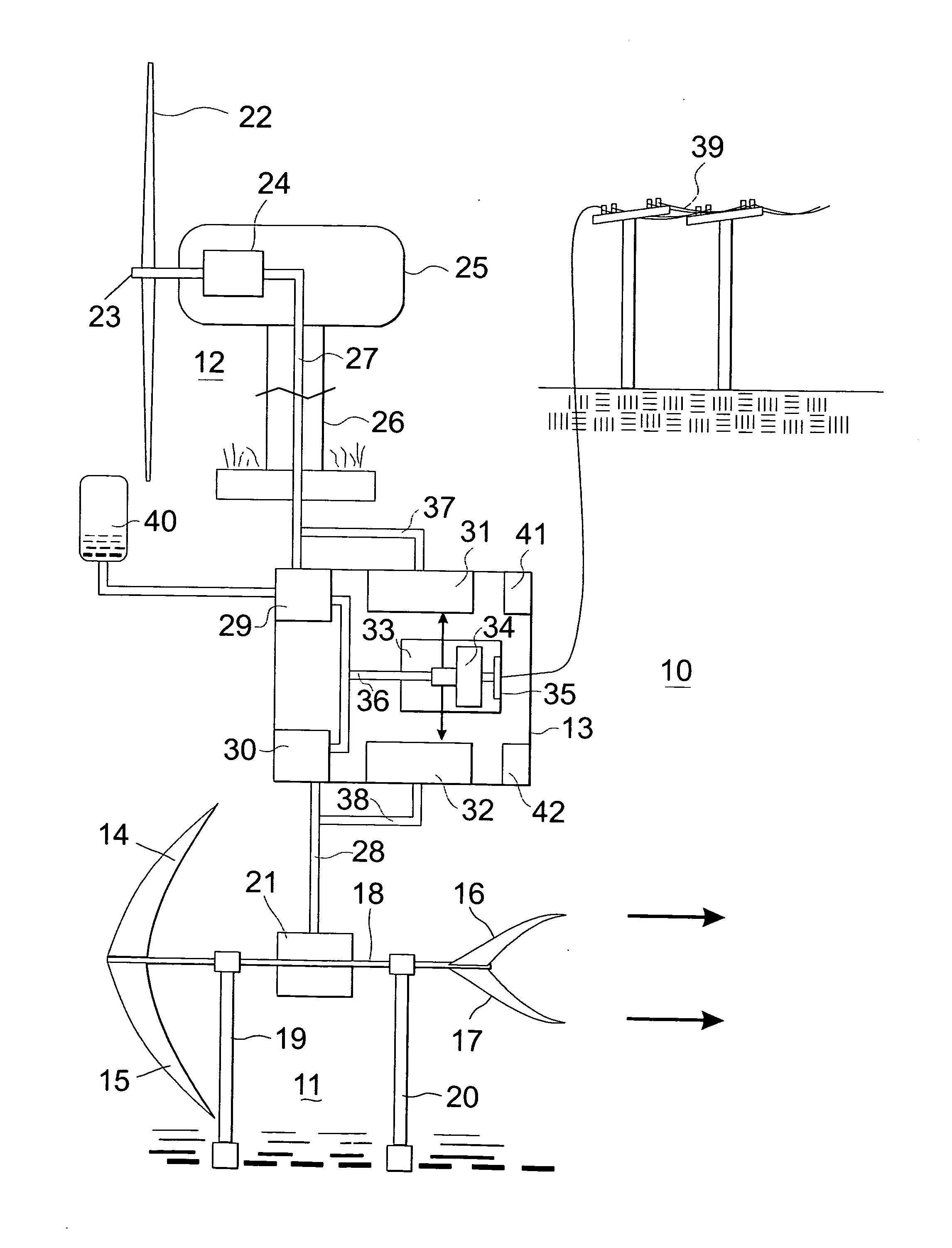
[0035]Referring now to the drawings, and first to FIG. 1, there is shown a schematic side view of a generating site, generally designated 10, which includes at least one tidal turbine 11 and at least one wind turbine 12. Both the tidal turbine 11 and the wind turbine 12 have hydraulic drive-trains for converting the kinetic energy of the water currents and of the wind currents into hydraulic (fluid) energy. The fluid energy from both systems is directed to a hydraulic fluid control system housed in enclosure 13 where the fluid energy is converted back into mechanical rotational energy for spinning a coupled generator generating electricity for input into the grid 39. The term at least one indicates that in the schematic at least one wind turbine and at least one tidal turbine are used in combination at the site, but there may be more than one wind system and more than one tidal system in the combination. During operation, a plurality of wind turbines (12) and a plurality of tidal tu...


PUM


Abstract

Tidal and wind turbines utilize a hydraulic drive-train to transfer the kinetic energy in moving currents to a generator located ground level for producing electricity for the grid. A rotor shaft transfers the mechanical energy from the rotors to a hydraulic pump which converts the mechanical energy into fluid energy which is transferred to a high pressure manifold and then to hydraulic motor for converting the fluid energy into rotational mechanical energy which spins a generator coupled to the motor. A high pressure manifold is coupled to a hydraulic accumulator for storing the fluid energy for later use.

Description

BACKGROUND OF THE INVENTION[0001]1. Field of the Invention[0002]The present invention relates to an electrical generation system which includes tidal and wind turbines having hydraulic drive-trains which include a low-speed hydraulic pump driven at rotor speed by the kinetic energy in the water or wind currents pumping fluid into a high-pressure manifold coupled to a large hydraulic accumulator for storing energy where the pressurized fluid drives a hydraulic motor coupled to a generator for generating electricity.[0003]2. Description of the Prior Art[0004]There has been a recent surge of interest in using renewable fuel sources to generate electricity. The public is concerned with pollution and the eventual depletion of carbon based fuels, and the utility companies are concerned with Renewable Energy Mandates which require that a certain percentage of their retail electricity come from renewable energy sources. In the US, state and federal mandates require approximately 10 percent ...

Claims


Application Information

Patent Timeline
Patent Type & Authority Applications(United States)
IPC IPC(8): F03B13/00F03B13/26F03D9/00
CPCF03B13/264F03D9/008F05B2260/406F05B2260/42Y02E10/30Y02E10/72Y02P80/10F03D9/255Y02E10/20
Inventor CARR, FRED K.
Owner CARR FRED K
Why Eureka
Try Eureka