
Solar cell and method of manufacturing the same

a technology of solar cells and passivation layers, which is applied in the field of solar cells, can solve the problems of reducing the efficiency of solar cells, so as to minimize the damage of passivation layers, minimize the extinguishing of carriers, and minimize the loss of photoelectric current

Inactive Publication Date: 2014-03-13
HANWHA CHEMICAL CORPORATION
View PDF5 Cites 8 Cited by
  • Summary
  • Abstract
  • Description
  • Claims
  • Application Information

AI Technical Summary

Benefits of technology

The present invention is a solar cell and a method of manufacturing it that have advantages in minimizing surface defects, reducing extinguishment of carriers, and increasing photoelectric efficiency. Additionally, the invention reduces manufacturing costs and allows for the production of large amounts of solar cells. The technical effects of the invention include the use of passivation layers on the light-receiving surface and the opposite surface of the solar cell, minimizing the loss of photoelectric current attributable to surface defects, and covering first electrodes with second electrodes to decrease serial resistance. The invention also eliminates the need for multiple stages of electrode pattern formation and minimizes damage to the passivation layer.

Problems solved by technology

However, when metal electrodes are formed on the semiconductor substrate using a punch through process, the damage of the passivation layer serving to reduce surface defects in the semiconductor substrate cannot be avoided.
Therefore, since the passivation layer is partially damaged in the process of forming the metal electrodes using a punch through process, surface defects causing the recombination of carriers increase, thus decreasing the efficiency of a solar cell.
However, this method is not suitable to manufacture a low-price high-efficiency solar cell because the processes thereof are complicated and lithography is expensive.
As described above, in order to realize a local electrode structure, conventionally, methods of forming a pattern for forming electrodes by removing a passivation film using lithography, chemical etching or lasers have been used, but these methods are problematic in that manufacturing costs increase due to the increase in the number of processes, and thus it is difficult to commercialize these methods.
That is, even though a local electrode structure is realized by these conventional methods, these conventional methods can be practically applied only when the efficiency of a solar cell is increased to such a degree that the efficiency thereof offsets and exceeds the increase in cost due to the introduction of the new processes, so it is difficult to apply these methods to the commercialization of a solar cell.
Moreover, these methods are problematic in that the line width and thickness of metal electrodes decrease, so resistance increases, thereby causing the efficiency of a solar cell to decrease.

Method used


Image

  • Solar cell and method of manufacturing the same
  • Solar cell and method of manufacturing the same
  • Solar cell and method of manufacturing the same

Examples


Embodiment Construction

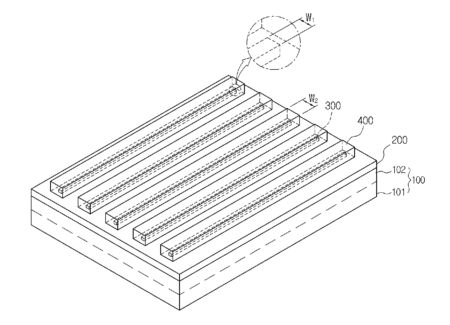
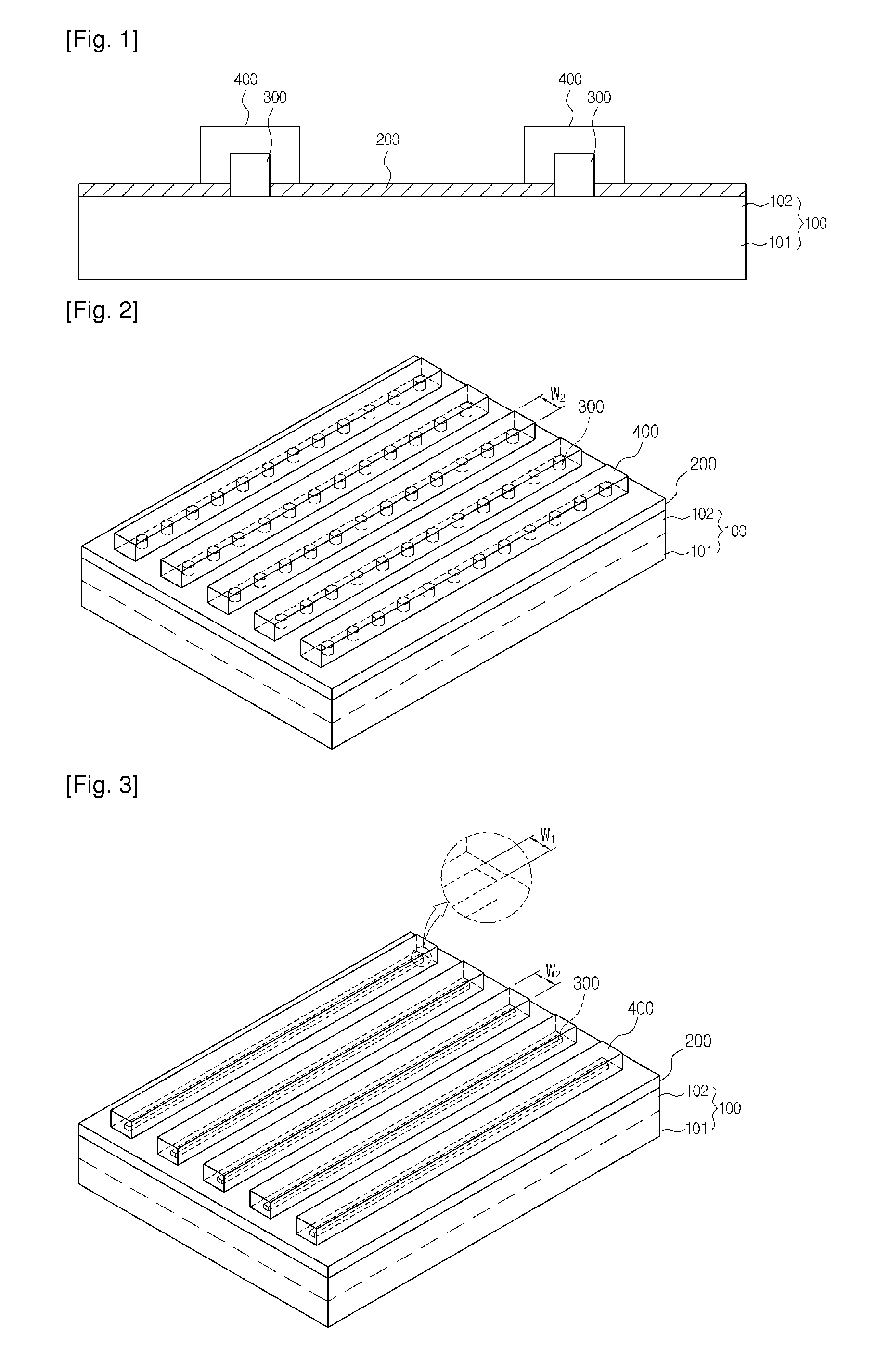
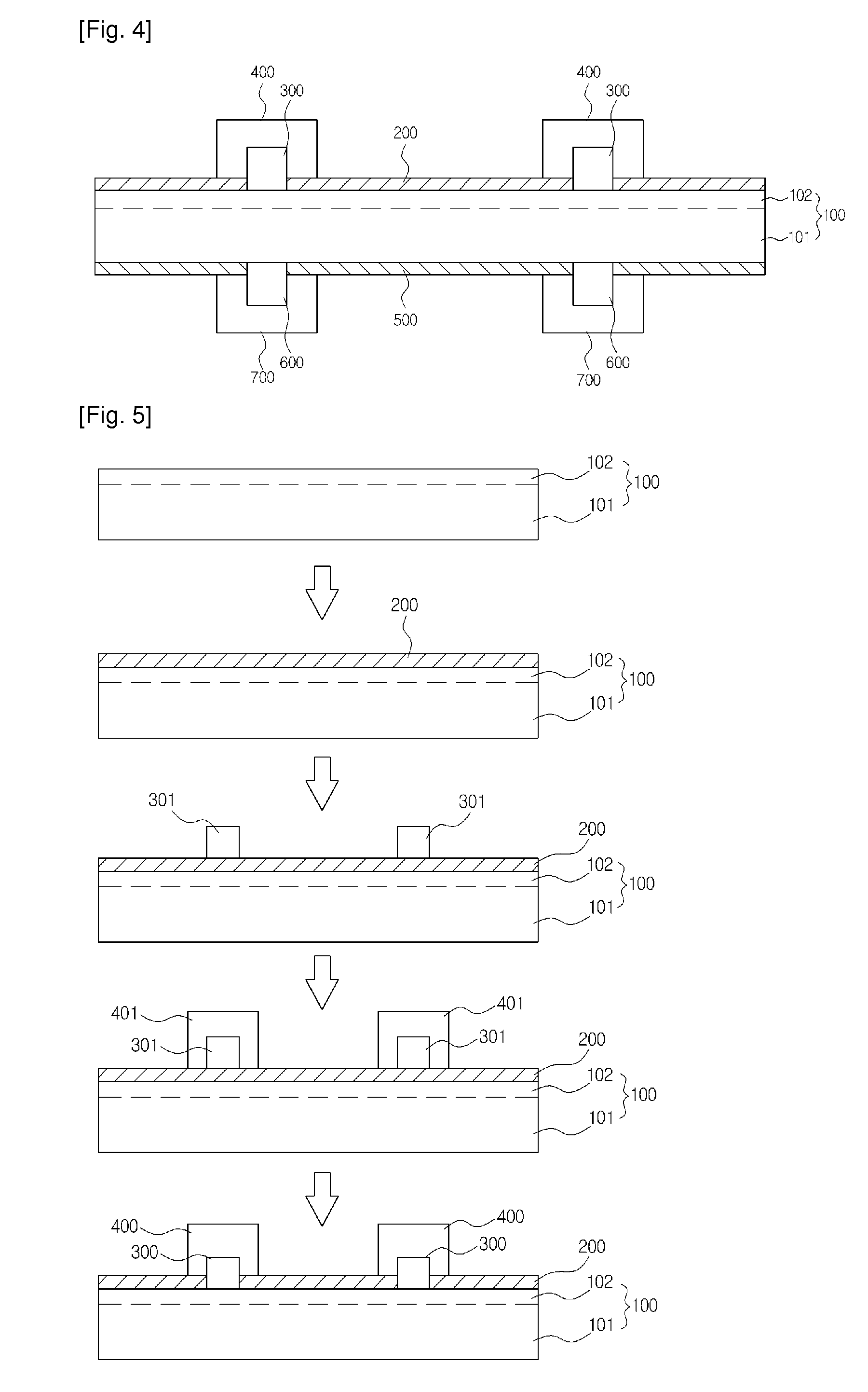
[0035]100: semiconductor substrate having p-n junction[0036]200, 500: antireflection film[0037]101: p-type impurity doped region[0038]102: n-type impurity doped region[0039]300, 600: first electrode[0040]301, 601: first electrode[0041]400, 700: second electrode[0042]401, 701: second electrode[0043]W1: width of first electrode[0044]W2: width of second electrode

MODE FOR THE INVENTION

[0045]Hereinafter, preferred embodiments of the present invention will be described in detail with reference to the accompanying drawings. The following drawings are provided for those skilled in the art as examples in order to sufficiently explain the technical idea of the present invention. Therefore, the present invention may be modified in various forms without being limited to the following drawings, and these following drawings may be exaggerated to clearly explain the technical idea of the present invention. Further, throughout the accompanying drawings, the same reference numerals are used to desig...


PUM


Abstract

Provided is a solar cell, including: a semiconductor substrate having a p-n junction; an antireflection film formed on at least one side of the semiconductor substrate; first electrodes formed on the antireflection film; and second electrodes covering the first electrodes, wherein only the first electrodes selectively penetrate the antireflection film and is thus connected with the semiconductor substrate by a punch through process.

Description

TECHNICAL FIELD[0001]The present invention relates to a solar cell and a method of manufacturing the same, and, more particularly, to a solar cell which can minimize surface defects attributable to the contact of a semiconductor substrate with electrodes and which has very low electrode resistance, and a method of manufacturing the same.BACKGROUND ART[0002]Silicon solar cells were developed in the 1950's, and have since been improved by decreasing the surface defects of the substrate with silicon surface passivation technology using a silicon oxide film, the passivation technology having started to be used in the field of microelectronics by in the 1980's, and thus greatly increasing voltage and current. As a result, the high-efficiency solar cell age was brought about.[0003]Factors influencing the efficiency of a semiconductor-based inorganic solar cell, which is the most general solar cell, are largely classified into three types.[0004]The first factor for increasing the efficienc...

Claims


Application Information

Patent Timeline
IPC IPC(8): H01L31/0216H01L31/0224
CPCH01L31/022425H01L31/02168Y02E10/50H01L31/06H01L31/0224H01L31/04
Inventor CHO, JAE EOCKLEE, YONG HWALEE, DONG HORYU, HYUN CHEOLKIM, GANG ILHYUN, DEOC HWAN
Owner HANWHA CHEMICAL CORPORATION
Learn More