Gas component detection device

a gas component and detection device technology, applied in the direction of instruments, color/spectral properties measurements, material analysis, etc., can solve the problems of reducing affecting the detection affecting the accuracy of gas components, etc., to suppress the decrease in the amount of infrared rays received.

Active Publication Date: 2014-03-13
PANASONIC INTELLECTUAL PROPERTY MANAGEMENT CO LTD
View PDF5 Cites 36 Cited by
  • Summary
  • Abstract
  • Description
  • Claims
  • Application Information

AI Technical Summary

Benefits of technology

[0027]The gas component detection device of the present invention has an effect of suppressing the decrease in the amount of a received infrared ray attributable to the incidence angle dependence of a wavelength filter.

Problems solved by technology

Therefore, the wavelength filter has a drawback in that the incidence angle dependence thereof is high.
Further, when the amount of the infrared rays passing through the wavelength filter and reaching the infrared detector or the optical receiver decreases, the detection accuracy of gas components declines.

Method used


Image

  • Gas component detection device
  • Gas component detection device
  • Gas component detection device

Examples


first embodiment

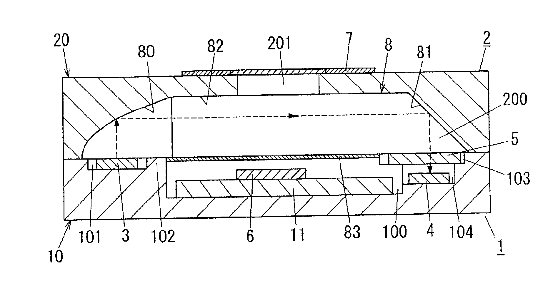
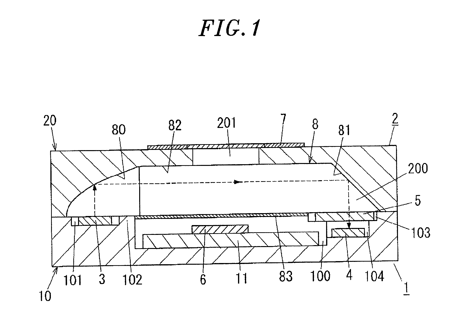
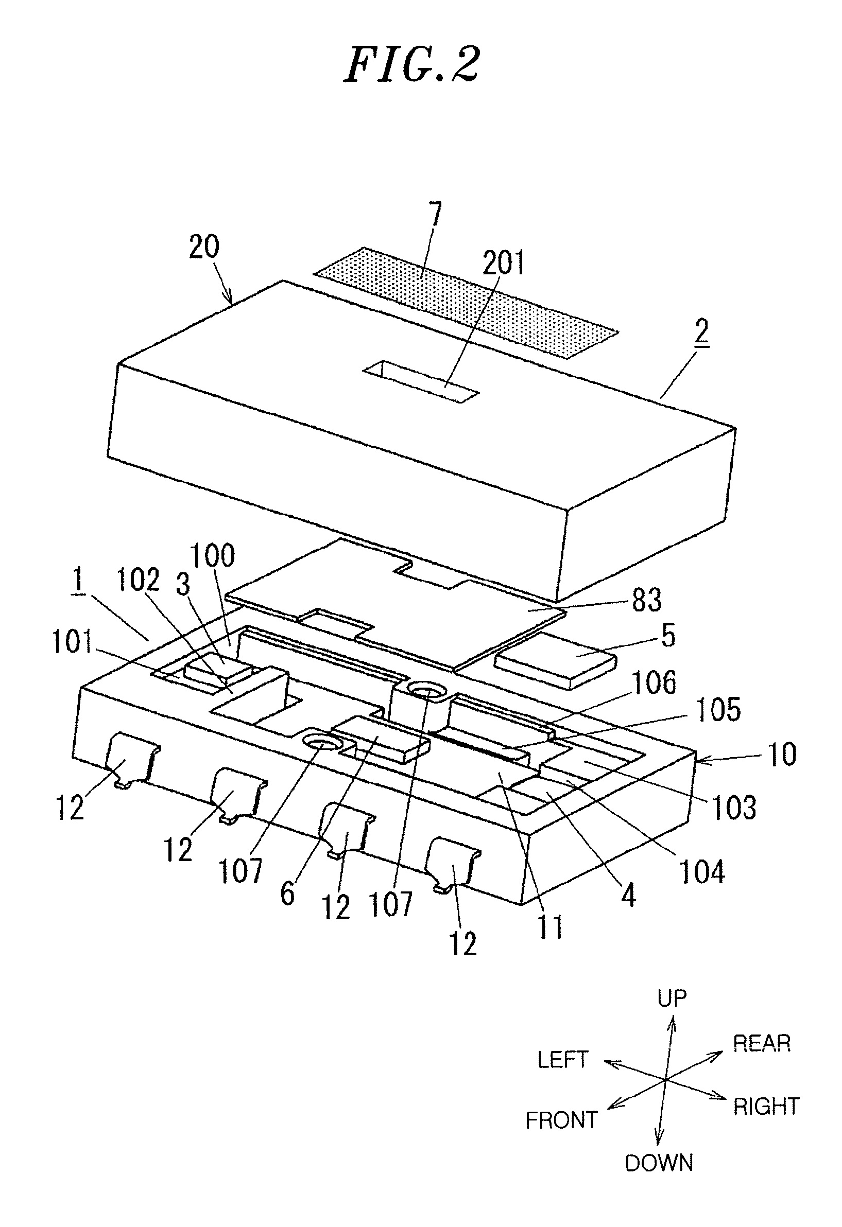
[0042]Referring to FIG. 2, a gas component detection device (hereinafter referred to as a “gas sensor”) in accordance with the present embodiment includes a circuit block 1 and an optical block 2. In the following description, up-down, left-right, and front-rear directions will be defined on the basis of FIG. 2.

[0043]The circuit block 1 includes a body 10 formed of a synthetic resin molded body and a wiring substrate 11 accommodated within the body 10. A light emitting unit 3, a light receiving unit 4, a wavelength filter 5 and a signal processing circuit unit 6 are mounted on the wiring substrate 11. The light emitting unit 3 is formed of a semiconductor bare chip for emitting infrared rays (e.g., a light emitting diode chip or a light source obtained by forming a resistor element on a semiconductor substrate using a micro electro-mechanical systems (MEMS) technology). The wavelength of the infrared rays emitted from the light emitting unit 3 is susceptible to absorption to a detec...

second embodiment

[0062]A gas sensor in accordance with the present embodiment is shown in FIG. 7. The gas sensor of the present embodiment is characterized by including two groups of the light receiving unit 4 and the wavelength filter 5. Other configurations remain the same as those of the first embodiment. Therefore, the same components as those of the first embodiment will be designated by like reference symbols, and redundant illustrations and descriptions thereof will be omitted.

[0063]As shown in FIG. 7, two lower depressed portions 104A and 104B are formed along the front-rear direction in the right end region of the upper surface of the body 10. A first light receiving unit 4A and a second light receiving unit 4B are mounted on the bottom surfaces of the lower depressed portions 104A and 104B, respectively. A first wavelength filter 5A and a second wavelength filter 5B are arranged on the bottom surface of the upper depressed portion 103 so as to cover the upper surfaces of the light receivin...

third embodiment

[0067]A gas sensor according to the present embodiment is shown in FIGS. 9A and 9B. The gas sensor of the present embodiment is characterized in the configuration of the optical block 2. Other configurations remain the same as those of the second embodiment. Therefore, the same components as those of the second embodiment will be designated by like reference symbols and redundant illustrations and descriptions thereof will be omitted.

[0068]In the present embodiment, as shown in FIG. 9B, the light guide body 8 includes a dividing portion 203 protruding downward from the bottom surface of the recess portion 200 of the cover 20. The dividing portion 203 is formed of a wedge-shaped wall tapering toward the leading end (left end). The rear end (right end) of the dividing portion 203 is positioned between the first light receiving unit 4A and the second light receiving unit 4B to divide the optical path of the infrared rays reflected by the first reflecting mirror 80 into two optical path...


PUM

PropertyMeasurementUnit
opticalaaaaaaaaaa
wavelengthaaaaaaaaaa
reflectionaaaaaaaaaa

Abstract

An optical path of infrared rays (see the broken lines in FIG. 1) is modified to a substantially U-like shape by a first reflecting mirror and a second reflecting mirror. An incidence angle of the infrared rays incident on the wavelength filter (an angle between the infrared rays incident on the surface of the wavelength filter and the line perpendicular to the surface of the wavelength filter) is nearly zero. For this reason, as compared with a conventional example, the influence of the incidence angle dependence of the wavelength filter can be reduced. As a result, the amount of the infrared rays reaching the light receiving unit through the wavelength filter is increased, thereby suppressing a decline in the detection accuracy of the gas component.

Description

FIELD OF THE INVENTION[0001]The present invention relates to a gas component detection device for detecting a gas component concentration using an absorption property of infrared rays.BACKGROUND OF THE INVENTION[0002]As the conventional gas component detection devices, there are available an infrared gas detector disclosed in Patent Document 1 and an infrared gas analyzer disclosed in Patent Document 2.[0003]The conventional example disclosed in Patent Document 1 includes a housing into which a detection target gas (e.g., carbon monoxide) is introduced, a light source for irradiating infrared rays into the housing, and an infrared detector for detecting infrared rays existing within the housing. The light source is formed of a package-type light emitting diode which includes a light emitting diode chip (a bare element), a stem to which the bare element is mounted and an encapsulation material for encapsulating the bare element. The light source emits infrared rays as an electric pow...

Claims


Application Information

Patent Timeline
Patent Type & Authority Applications(United States)
IPC IPC(8): G01N21/17G01N21/35G01N21/3504
CPCG01N21/17G01N21/3504
Inventor MATSUSHIMA, SHUNSUKEFURUKUBO, EIICHI
Owner PANASONIC INTELLECTUAL PROPERTY MANAGEMENT CO LTD
Why Eureka
Try Eureka