Solar lighting apparatus and system thereof

a technology of solar energy and lighting apparatus, which is applied in the direction of lighting and heating apparatus, lighting support devices, and with built-in power, etc., can solve the problems of high cost of making solar energy available for use, inconvenient installation, and inability to explode the use of solar energy for household products. , to achieve the effect of convenient installation, increased power, and increased siz

Active Publication Date: 2014-03-13
IP POWER HLDG
View PDF6 Cites 9 Cited by
  • Summary
  • Abstract
  • Description
  • Claims
  • Application Information

AI Technical Summary

Benefits of technology

[0011]Another advantage of the invention is to provide a solar lighting apparatus which includes a lighting apparatus and a solar panel arrangement for providing solar panel units in which the solar panel units are not restricted to position at a top surface of a light apparatus body of the light apparatus, thereby exploiting the possibility of providing a solar panel unit having a larger size than the light apparatus body and the possibility of providing a light emitting unit of the light apparatus requiring higher power. Accordingly, the solar lighting apparatus can be expanded to be used in street light, entrance light, outdoor lamp and etc.
[0012]Another advantage of the invention is to provide a solar lighting apparatus which includes a lighting apparatus and a solar panel arrangement for providing solar panel units in which the solar panel units are not restricted to position at a top surface of the light apparatus body of the lighting apparatus, thereby providing design flexibilities for fitting different household needs.
[0013]Another advantage of the invention is to provide a solar lighting apparatus which includes a light apparatus and a solar panel arrangement for providing solar panel units which is adjustable to face different cardinal points.
[0014]Another advantage of the invention is to provide a solar lighting apparatus which includes a wiring arrangement having a plurality of connecting wire units so as to facilitate easy installation while providing flexibility in length adjustment.
[0015]Another advantage of the invention is to provide a solar lighting apparatus which includes a lighting apparatus comprising a light emitting unit and a light apparatus body, a solar panel arrangement providing solar panel unit in which the solar panel unit is not restricted to a position on the light apparatus body of the lighting apparatus, and a wiring arrangement having a plurality of connecting wire units connecting between the light emitting unit and the solar panel unit of the solar panel arrangement, thereby the light apparatus body is free from direct connection to the solar panel arrangement and therefore at least a part of the light apparatus body is capable of being detachable from the light apparatus body for easy replacement.
[0016]Another advantage of the invention is to provide a solar lighting apparatus which includes a lighting apparatus comprising a light emitting unit and a light apparatus body, a wiring arrangement having a plurality of connecting wire units, and a solar panel arrangement for providing a solar panel unit connected to the light emitting unit through the connecting wire unit such that a plurality of light apparatus bodies of different designs can be provided for the solar lighting apparatus to fit the market needs.

Problems solved by technology

In the past, the cost of making solar energy available for use was at a very high level and the effectiveness of utilization is not satisfactory.
Therefore, it is not cost-effective to explode the use of solar energy for household products which require a low energy requirement, even though the accumulated sum of energy requirement is substantively high.
However, the installation and equipment cost is still very high.
However, this early development and exploitation of solar energy is not effective and has the following drawback.
First, this is only suitable for low power pathway light apparatus because the solar panel positioned at the top surface is limited by the size of the light apparatus and the power of the light apparatus is limited by the size of the solar panel.
In other words, this utilization is limited to low powered pathway light apparatus.
In general, the pathway light apparatus may not be able to provide illumination for the whole night.
Second, the position of the solar panel is fixed relative to the light apparatus and therefore the solar panel fails to adapt to any changes of solar light direction.
Third, the brightness of illumination is not adjustable and no mechanism is provided in relation to brightness adjustment to fit the day-night cycle of a day.
There lacks any mechanism of control to effectively adapt the power consumption cycle of the pathway light in consistent to the requirement in the day-night cycle.
Fourth, the power consumption of the light apparatus fails to equip with non-sunny days, such as rainy days or cloudy days.
Since there is no light adjustable or control mechanism, the light apparatus is not prepared to face any non-sunny days and simply does not work during rainy or cloudy days.
Fifth, the problem of insufficient charging during a particular cycle has greatly lowered the efficiency and the lifespan of the lighting apparatus.
Since weather is unpredictable and the light apparatus has only one rigid cycle involving on / off status, insufficient charging is common and the lifespan of the lighting apparatus is shorter than expected.
In other words, the light apparatus fails to adapt to the weather which involves abnormal operation of the light apparatus and therefore the lifespan is short and hence the efficiency is low.
The conventional garden pathway light apparatus also has other undesirable constraints in relation to its structural.
However, when a level of hardness of the ground surface is very high, it is not possible to position the light apparatus onto the ground surface.
When the only available ground surface is concrete, the light apparatus lacks any structural elements for support and therefore cannot be positioned on top of a concrete surface.
In other words, the light apparatus is only suitable for use in relatively soft ground surface.
In addition, because of the lack of supporting mechanism, the light apparatus is limited in utilization, which is garden pathway light for use in a garden with soil or sand ground surface.
The conventional garden pathway light apparatus is limited in shape and design because of the position requirement of the solar panel.
Accordingly, the shape and design of the light apparatus is restricted.

Method used


Image

  • Solar lighting apparatus and system thereof
  • Solar lighting apparatus and system thereof
  • Solar lighting apparatus and system thereof

Examples


first embodiment

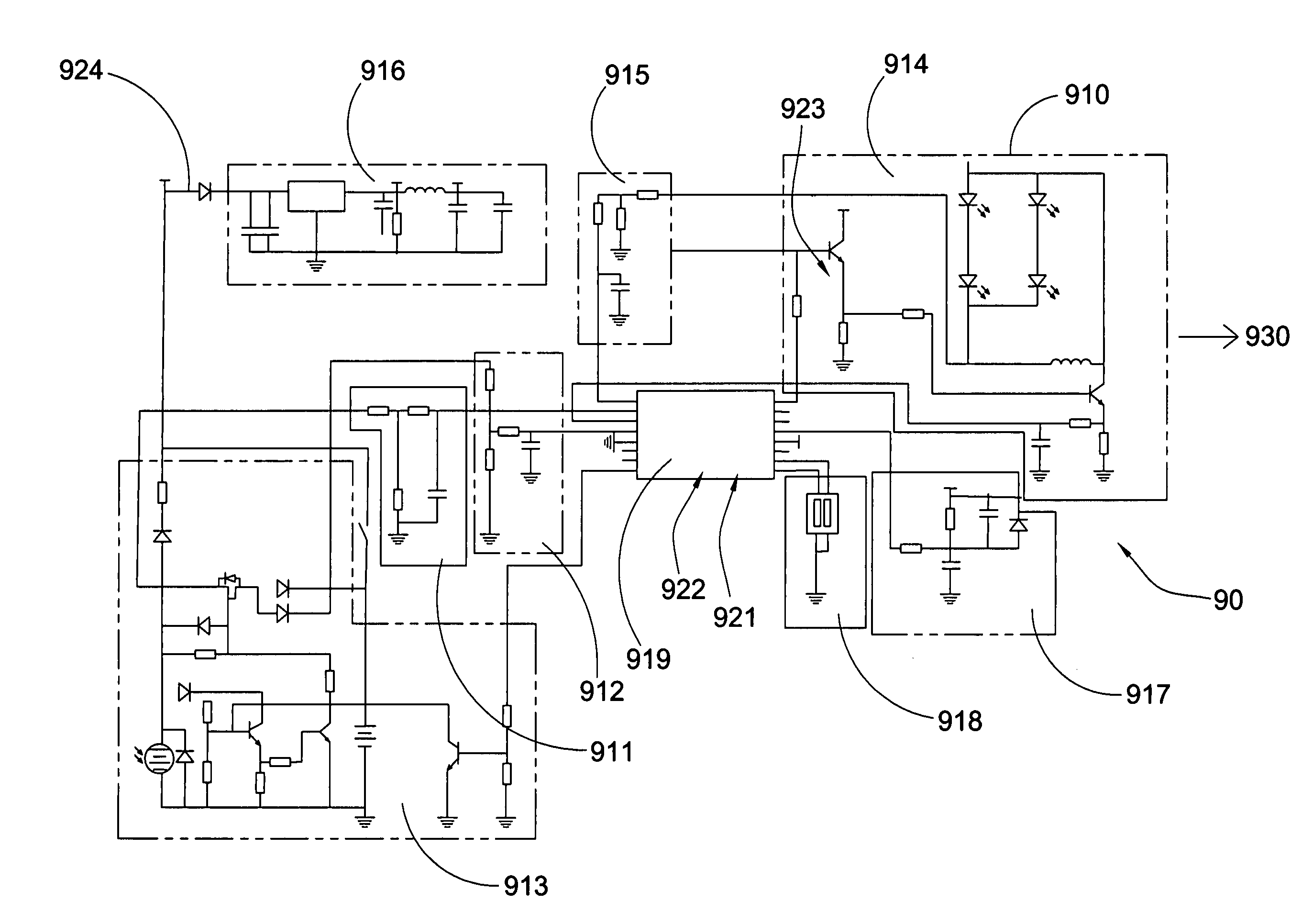
[0104]Preferably, as shown in FIG. 16 of the drawings, the control circuit 910 according to the preferred embodiment of the present invention comprises a D3 diode 924 provided and connected to the MCU power supply circuit 916 to provide protection against reverse connection between the positive and the negative terminals at a position between the charge control circuit 913 and the MCU power supply circuit 916.

second embodiment

[0105]Preferably, as shown in FIG. 16 of the drawings, the control circuit 910 according to the preferred embodiment of the present invention has a preset chip voltage of the light control circuit 911 which is divided through two resistance unit R14 and R23, which is then inputted into a port 9PA2 of the MCU 919 and is compared through a AD digital conversion circuit in the MCU 9 to control a turn on and a turn off action to the LED lighting system 930.

third embodiment

[0106]Preferably, as shown in FIG. 16 of the drawings, the control circuit 910 according to the preferred embodiment of the present invention further comprises a DIP switch 918 provided and connected to a port PB3 and a port PB4 of the MCU 919. Preferably, the MCU 919 is a 46R065 series MCU.

[0107]The light control circuit 911 is arranged for controlling on / off status of the LED lighting system 930 through detecting a voltage of solar panel. The voltage of the solar panel is divided by the R23 and R14, inputted into the MCU 919 through port PA2, and transformed into the required data by the MCU 919. The data is then analyzed and compared with a preset database so as to determine whether it is required to turn on or turn off the LED light. This construction can effectively prevent transient occurrence of light flashing due to change of lighting status of the LED light. In addition, if the LED light is turned on, the LED light will not be turned off even a light source which is below 8...


PUM


Abstract

A solar lighting apparatus and system, which is constructed into a street lamp, entrance lamp, garden lamp, nightlight, etc., includes a light emitting unit for providing illumination and a lighting apparatus body; a solar energy arrangement including a solar panel unit for light absorption and power supply; and a mounting plate; at least one ground supporting unit coupling with the mounting plate for securing the mounting plate onto a ground surface; and a light apparatus connecting unit provided through the mounting plate for firmly positioning the lighting apparatus, and a LED light control arrangement effectively controlling a power consumption in such a manner that the light emitting unit is arranged to being charged and discharged in a controlled manner and is protected against short circuit and overcharging, thereby maximizing power utilization, increasing lifespan and performance of the solar lighting apparatus.

Description

BACKGROUND OF THE PRESENT INVENTION[0001]1. Field of Invention[0002]The present invention relates to, and more particularly to a solar lighting apparatus, and more particularly to a solar light apparatus which includes a wiring arrangement and a power control mechanism such that the solar light apparatus can provide an adjustable solar panel having a size independent to and unrestricted by the size of the light apparatus and therefore can provide higher power which is suitable for different uses such as a street lamp, a pathway light, an entrance light, an outdoor lamp while at the same has a control mechanism to effectively utilize the solar energy to fit the day-night cycle of a day and to prepare for providing illumination during non-sunny days.[0003]2. Description of Related Arts[0004]Energy crisis is an important issue for today's world and has led to recent development in relation to green energy and energy conservation method, both in industrial and household level. In partic...

Claims


Application Information

Patent Timeline
Patent Type & Authority Applications(United States)
IPC IPC(8): F21S9/03
CPCF21S9/035F21S2/00F21S6/005F21S9/032F21V21/06F21V21/0824F21W2131/10F21W2131/109F21Y2115/10Y02B10/10Y02B20/72
Inventor ZHU, SHOU QIANG
Owner IP POWER HLDG
Why Eureka
Try Eureka