Corrective optical systems and methods

Inactive Publication Date: 2014-03-27
CALDWELL PHOTOGRAPHIC
View PDF6 Cites 2 Cited by
  • Summary
  • Abstract
  • Description
  • Claims
  • Application Information

AI Technical Summary

Benefits of technology

[0008]The present disclosure is directed to corrective optical systems and methods for “correcting” (i.e., reducing or substantially eliminating) aberrations caused by one or more plane parallel plates (i.e., “flat plates”) that resides on the image side of an objective

Problems solved by technology

The addition of one or more flat plates between the objective and the image plane introduces aberrations i

Method used


Image

  • Corrective optical systems and methods
  • Corrective optical systems and methods
  • Corrective optical systems and methods

Examples


example 1

Corrector Example 1

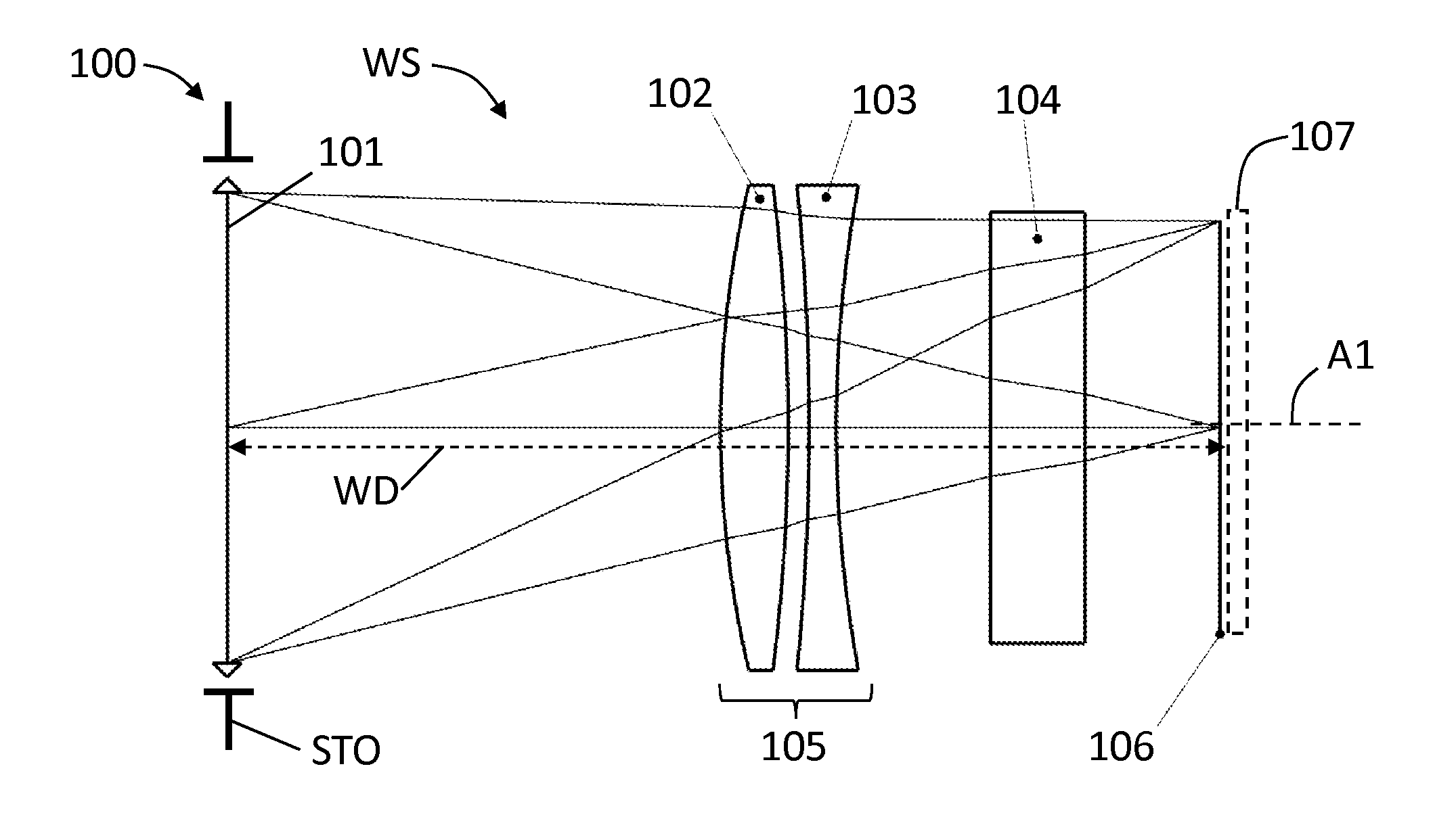
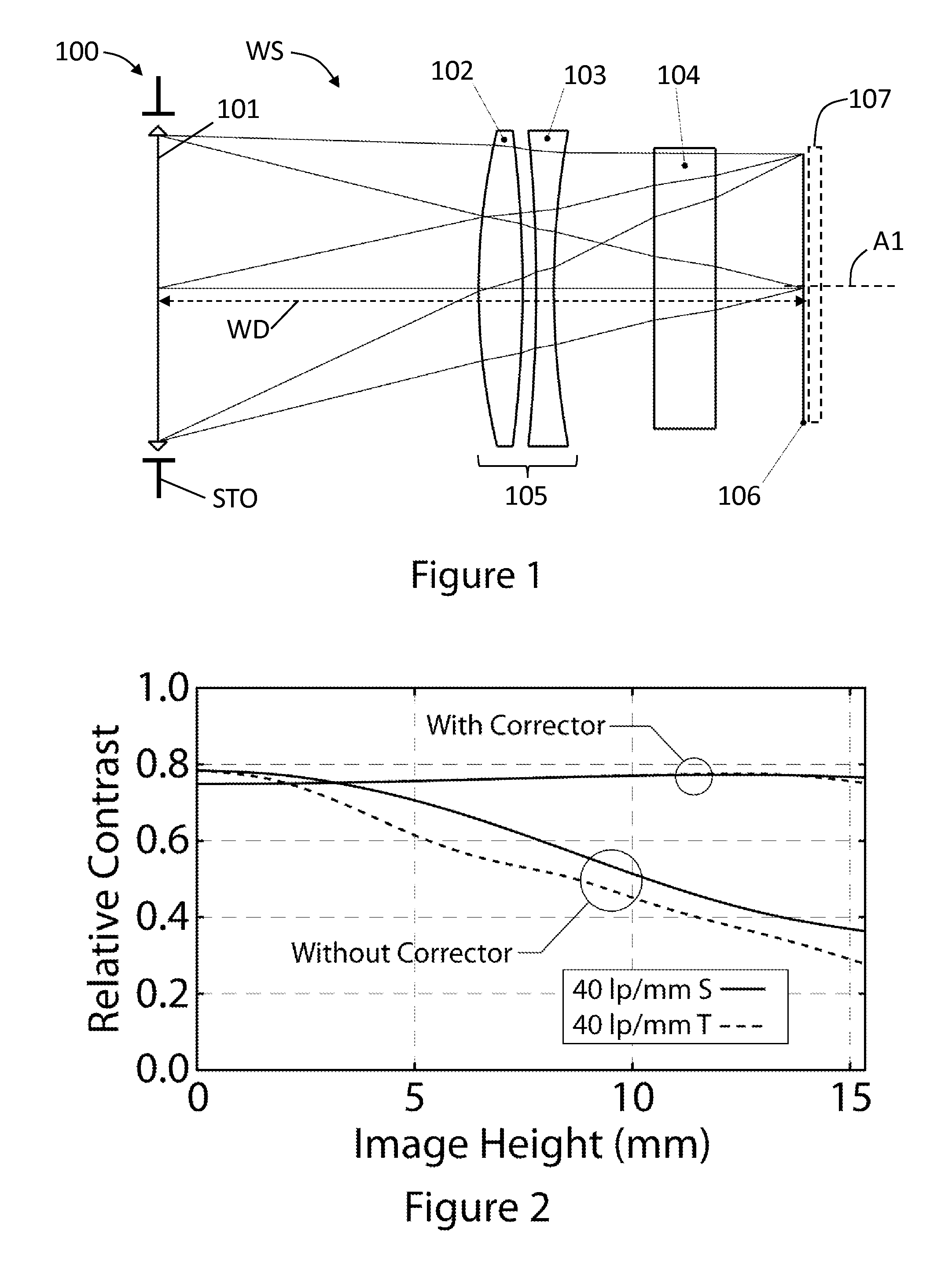
[0071]FIG. 1 is an optical diagram of an imaging optical system 100 that includes, along an axis A1, a perfect or ideal objective (“objective”) 101, a flat plate 104, and a first example (Example 1) corrective optical system (“corrector”) 105, which resides between the objective and the flat plate. Imaging optical system 100 has an image plane 106. Objective 100 has a working space WS between the objective 101 (more specifically, the rearmost lens element of the objective) and image plane 106. The working space WS has an associated working distance WD.

[0072]Corrector 105 is designed to be universal, which means that it can correct the aberrations introduced into a perfect objective 101 by flat plate 104. The perfect objective 101 is aberration-free only when it is used by itself, i.e., without any flat plates in the working space WS. Adding the flat plate 104 introduces a range of aberrations, including spherical aberration, coma, astigmatism, longitudinal chromat...

example 2

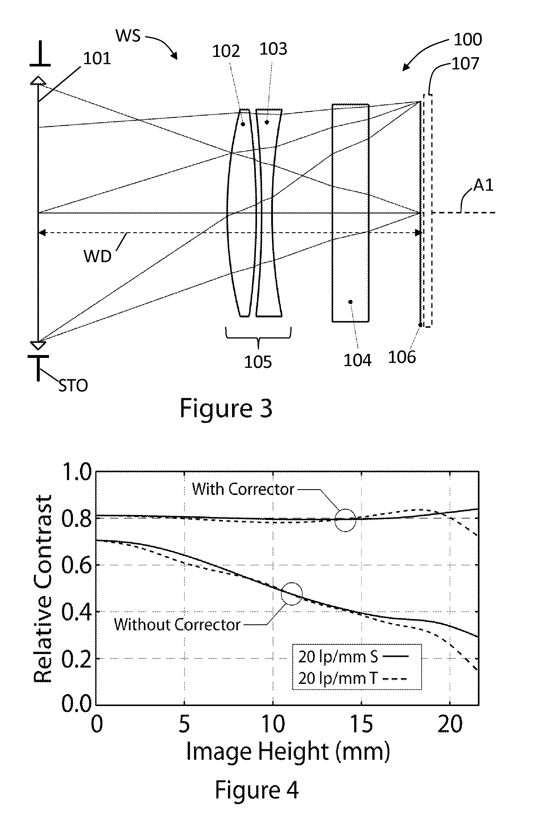
[0081]FIG. 3 shows a second example (Example 2) of imaging optical system 100, wherein corrector 105 is optimized for a large aperture (f / 1.4) and large image diagonal (43.26 mm). Corrector 105 of Example 2 is thus suitable for use with a full-frame 35 mm format (24 mm×36 mm) objective 101.

[0082]Corrector 105 of Example 2 is also designed as a universal corrector. Corrector 105 comprises, in order along axis A1 from objective 101 to image plane 106, a bi-convex positive powered lens element 102 and a bi-concave negative powered lens element 103.

[0083]To maximize the use of the available working space WS, corrector 105 has slightly negative optical power. This in turn requires that the positive element 102 be made from a material having a lower index of refraction than the negative element 103 to avoid introducing backward field curvature. As a result, the image plane 106 can be planar.

[0084]FIG. 4 shows two different plots of MTF vs. Image Height at a spatial frequency of 20 lp / mm. ...

example 3

[0087]FIG. 5 illustrates a third example (Example 3) of imaging optical system 100, wherein corrector 105 is designed as a custom corrector for a particular objective 101. Consequently, corrector 105 is optimized to correct the aberrations introduced by flat plate 104 in a known objective 101. The example known objective 101 is an 85 mm f / 1.4 design taken from the public domain patent literature, in this case U.S. Pat. No. 4,396,256, example #3 of 4. This design corresponds approximately to an 85 mm f / 1.4 lens manufactured by Nikon, Inc. The corrective optical system 105 comprises, in order from objective 101 to image plane 106, a bi-convex positive-powered lens element 102 and a bi-concave negative powered lens element 103.

[0088]FIG. 6 shows three different plots of MTF vs. Image Height at a spatial frequency of 20 lp / mm. The three plots are shown on the same graph so that they may be easily compared. The relative contrast for sagittal S and tangential T rays are shown as solid and...


PUM

PropertyMeasurementUnit
Lengthaaaaaaaaaa
Molar densityaaaaaaaaaa

Abstract

A corrective optical system for an imaging optical system is disclosed, wherein the imaging optical system has an objective having a working space, and whose imaging performance is not corrected for one or more plane parallel plates located in the working space. The corrector optical system resides in the working space between the one or more plane parallel plates and objective and serves to reduce the aberrations introduced by the one or more plane parallel plates. The corrector optical system enables objectives originally designed for film to be used with digital cameras.

Description

CROSS-REFERENCE TO RELATED APPLICATIONS[0001]This application claims priority under 35 USC §119(e) of U.S. Provisional Patent Application Ser. No. 61 / 704,785, filed on Sep. 24, 2012, and which is incorporated by reference herein.[0002]All references cited herein are incorporated herein by reference.FIELD[0003]The present disclosure is directed to corrective optical systems, and in particular to such system and methods for reducing aberrations in a primary or objective lens caused by the use of one or more plane parallel plates.BACKGROUND ART[0004]For many decades, photographic and cinematographic objective lenses (“objectives”) have been designed to work optimally with film at the image plane. In this configuration, there are typically no filters or other transparent plane parallel plates (hereinafter “flat plates”) located in the optical path between the objective and the image plane. An exception is telephoto lenses having a large entrance pupil diameter, which often include a rea...

Claims


Application Information

Patent Timeline
IPC IPC(8): G02B9/10H04N5/225
CPCH04N5/2254G02B9/10G02B27/0025G02B13/00G02B13/02Y10T29/49826H04N23/55
Inventor CALDWELL, J. BRIAN
Owner CALDWELL PHOTOGRAPHIC
Why Eureka
Try Eureka