Motion robust vital signal monitoring

a vital signal and robust technology, applied in the field of motion robust vital signal monitoring, can solve the problems of difficult monitoring conditions and constraints, difficulty in observing subjects, disturbances and restrictions, etc., and achieve the effect of improving detection accuracy and reliability, and reducing efforts

Inactive Publication Date: 2014-03-27
KONINKLJIJKE PHILIPS NV
View PDF3 Cites 51 Cited by
  • Summary
  • Abstract
  • Description
  • Claims
  • Application Information

AI Technical Summary

Benefits of technology

[0014]It is an object of the present invention to provide a device and a method for extracting physiological information from remotely detected electromagnetic radiation providing further refinements facilitating obtainment of the desired vital signals with reduced efforts. It would be further...

Problems solved by technology

Although considerable progress in the field of monitoring performance has been achieved, it is still a challenge to provide for instant signal recognition and signal processing enabling immediate, so-to-say, on-line detection of desired vital signals.
This applies in particular to hand-held mobile devices commonly lacking of sufficient computing power and typically exposed to challenging monitoring conditions and constraints.
A further challenge may arise from disturbances and restrictions which have to be taken into account for the detection of the desired signals.
Furthermore, referring to remote detection approaches, prior art devices and methods may require markers or similar items which have to be applied to the subject to be observed.
Still, however, obtrusive measurement, either applied remotely or via tactile measurement devices, is considered unpleasant and uncomfortable by many observed subjects.
Consequently, since no hardware markers are available, remote unobtrusive detection is widely subjected to disturbances.
Mobile hand-held devices are even more susceptible to disturbances si...

Method used


Image

  • Motion robust vital signal monitoring
  • Motion robust vital signal monitoring
  • Motion robust vital signal monitoring

Examples


Embodiment Construction

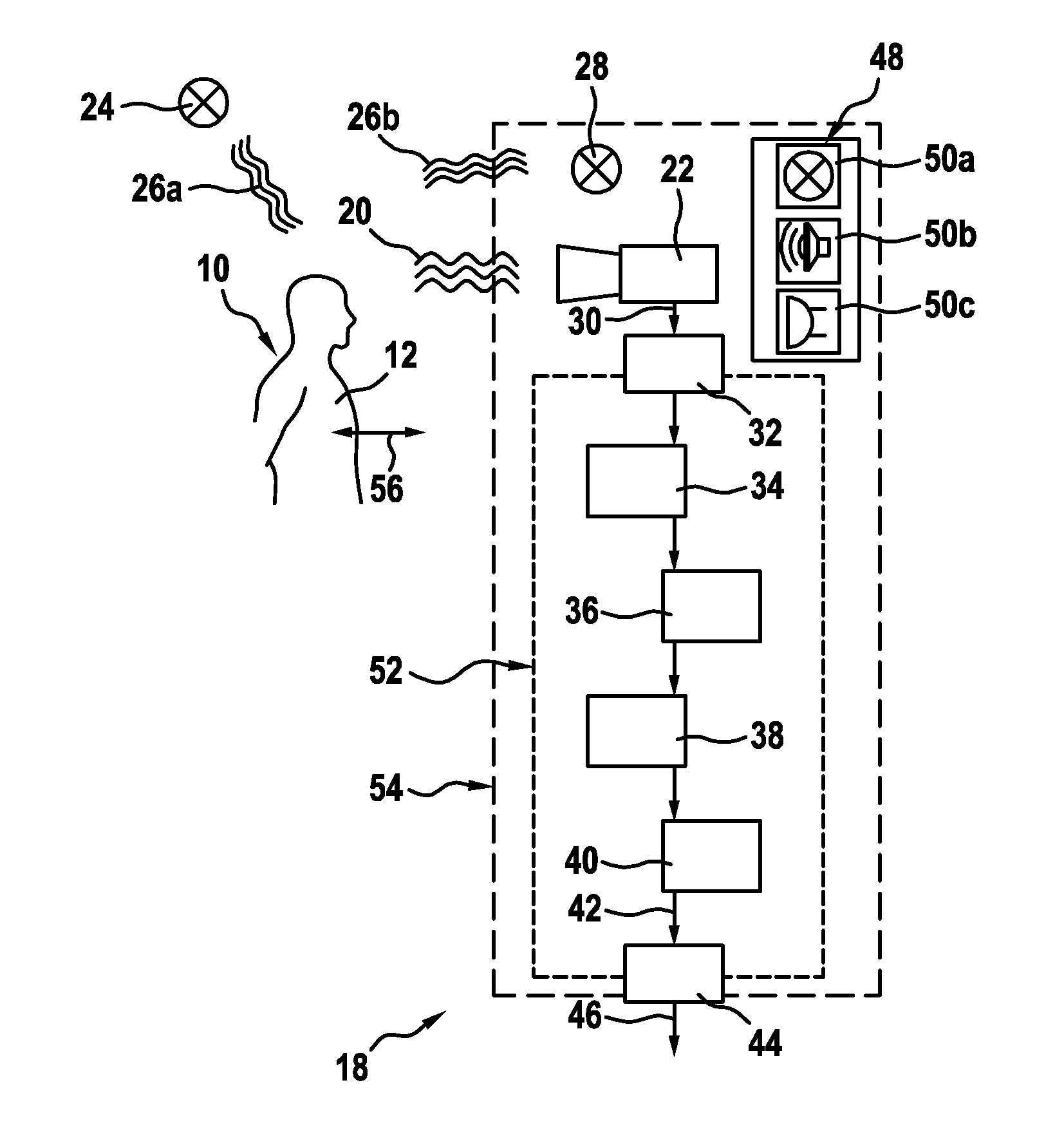
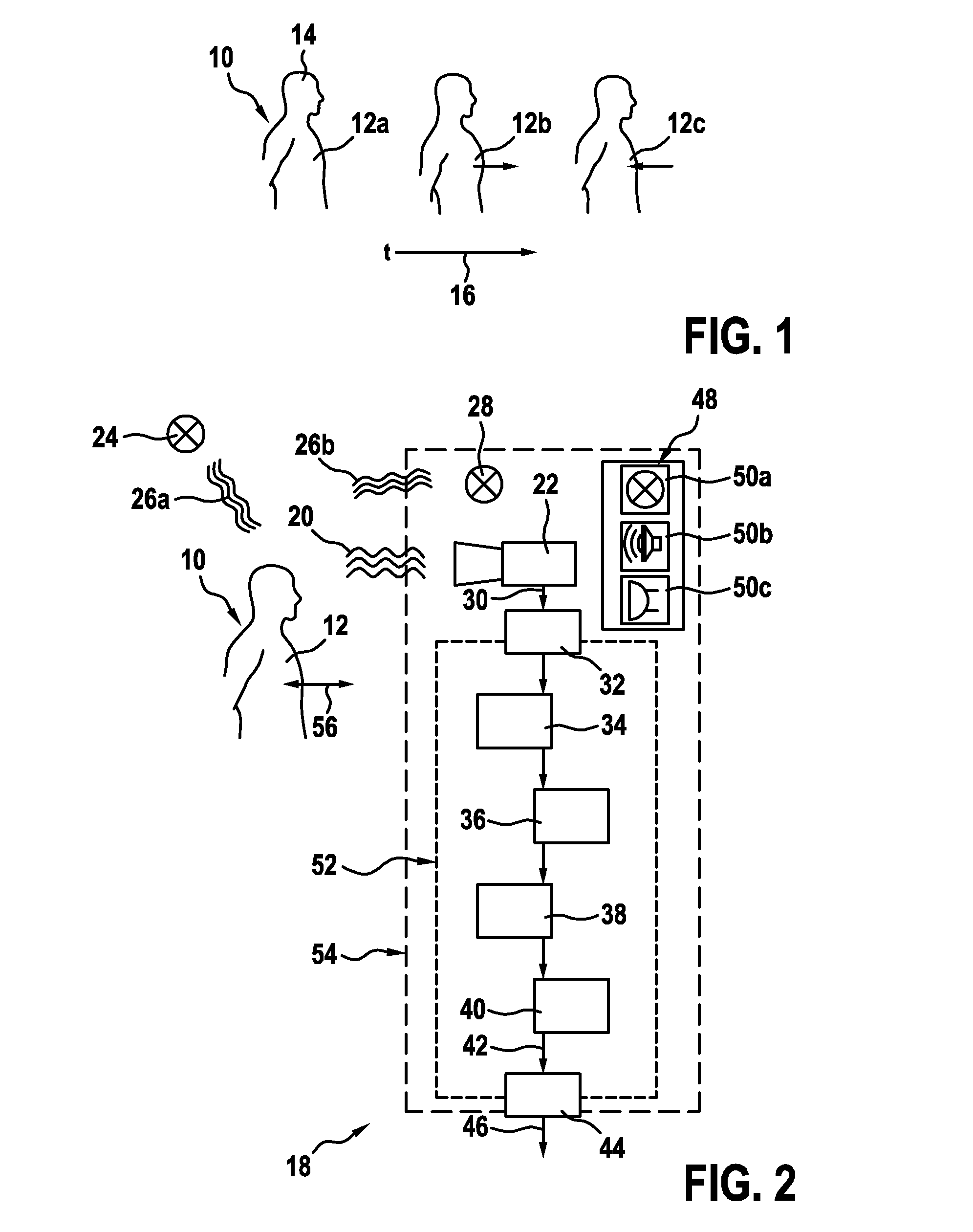
[0095]FIG. 1 shows a schematic illustration of a subject 10 which experiences motion indicative of a signal of interest. The subject 10 undergoes a characteristic motion of an indicative portion 12 due to respiration. When breathing, expansion and contraction of the lungs or the diaphragm causes slight motion of characteristic portions in living beings, in particular lifting and lowering of the chest. Also abdominal breathing can cause characteristic motion of respective parts of the subject's body. At least partially periodic motion patterns induced by various physiological processes can occurred in many living beings, particularly in humans or animals. Over time, as indicated by an arrow 16, the indicative portion 12 is moved between a contracted position, indicated by reference numerals 12a, 12c, and an extracted position, indicated by reference numerals 12b. By way of the example, based on this motion pattern (herein also referred to as physiological information 56, refer to FIG...


PUM


Abstract

The present invention relates to a device and a method for extracting physiological information from remotely detected electromagnetic radiation emitted or reflected by a subject. A data stream derivable from electromagnetic radiation emitted or reflected by a subject is received. The data stream comprises a sequence of signal samples indicative of desired subject motion and of disturbing motion. The signal samples represent at least one region of interest exhibiting an at least partially periodic indicative motion pattern attributable to at least one physiological parameter, and a non-indicative motion region. The sequence of signal samples is processed, comprising deriving a sequence of derivative motion compensated samples at least partially compensated for undesired overall motion; detecting an evaluation parameter representative of motion compensation accuracy; and deriving at least one characteristic signal at least partially indicative of the at least partially periodic indicative motion pattern from the sequence of motion compensated samples, wherein deriving the characteristic signal is performed depending on the detected evaluation parameter.

Description

CROSS REFERENCE TO RELATED APPLICATIONS[0001]This application claims the benefit of EP provisional application serial no. 12185469.9 filed Sep. 21, 2012 and U.S. provisional application Ser. No. 61 / 706,173 filed Sep. 27, 2012, both of which are incorporated herein by reference.FIELD OF THE INVENTION[0002]The present disclosure relates to a device and a method for extracting physiological information from remotely detected electromagnetic radiation emitted or reflected by a subject, wherein the physiological information is embodied in a data stream comprising a sequence of signal samples indicative of desired subject motion and of disturbing motion. The present disclosure further relates to a computer readable non-transitory medium.BACKGROUND OF THE INVENTION[0003]US 2010 / 0061596 A1 discloses a method of determining a similarity with a portion of a physiological motion, the method comprising the steps of:[0004]obtaining a first image of an object;[0005]obtaining a second image of the...

Claims


Application Information

Patent Timeline
IPC IPC(8): A61B5/00A61B5/08A61B5/113A61B5/024
CPCA61B5/721A61B5/0059A61B5/113A61B5/08A61B5/024G06T7/254G06T7/248A61B5/1128G06T2207/30076G06T2207/30104G06T2207/10016G06T2207/20224A61B5/00G06T7/246A61B5/0075A61B5/7207A61B5/7278A61B2560/0431A61B2560/0487A61B2576/00G06T2207/30004
Inventor SHAN, CAIFENG
Owner KONINKLJIJKE PHILIPS NV
Why Eureka
Try Eureka