Hf-Co-B Alloys as Permanent Magnet Materials
a permanent magnet material and alloy technology, applied in the direction of magnetic materials, basic electric elements, magnetic bodies, etc., can solve the problems of reducing the attractiveness of these materials, high coercivity, and strong anisotropy
- Summary
- Abstract
- Description
- Claims
- Application Information
AI Technical Summary
Benefits of technology
Problems solved by technology
Method used
Image
Examples
example i
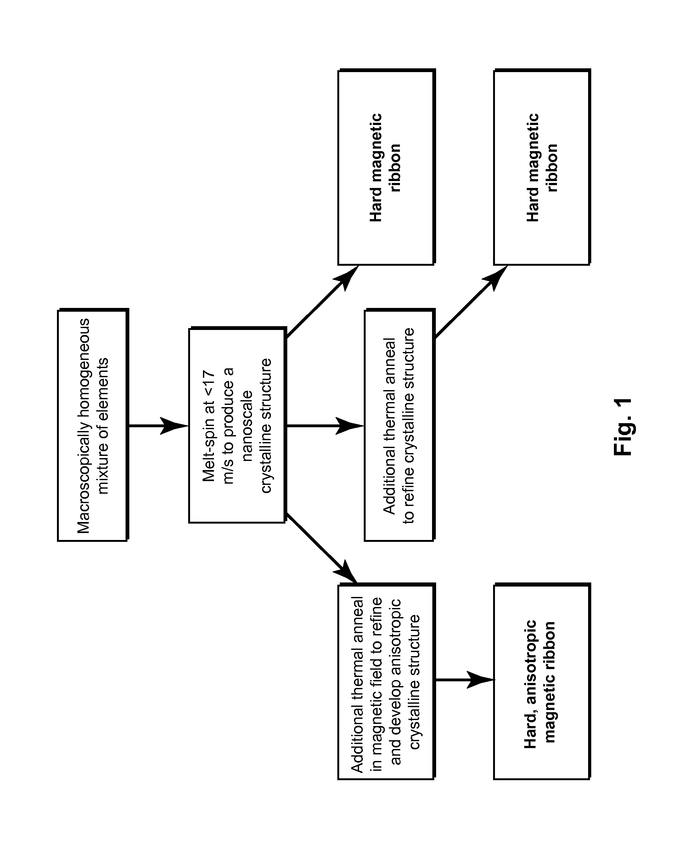
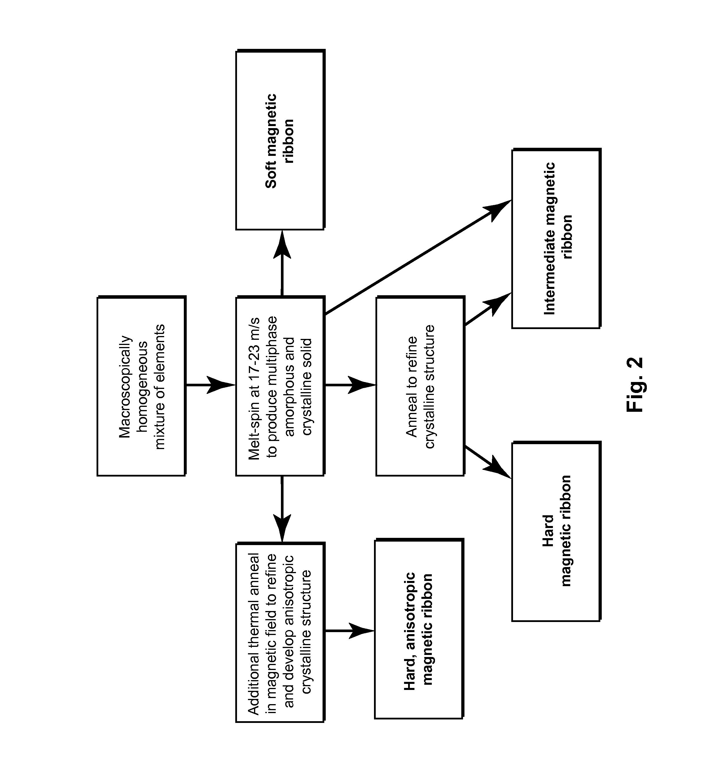
[0055]Alloys of composition Hf2Co11B were made from cobalt slugs (99.95%), hafnium pieces (99.9% excluding Zr, nominal 2% Zr), and boron pieces (99.5%) by arc-melted under argon. The resulting slugs were inverted and remelted several times, and had a total mass of approximately 5 g each. The density of the alloy was determined to be 10.7 g / cm3 from the measured mass and dimensions of a cylindrical, suction-cast rod. Melt-spinning was conducted by induction heating the samples to above the melting temperatures (Tmelt≈1500 K) in silica crucibles and ejecting them through a 0.5 mm orifice onto a 30 cm diameter, 1.2 cm thick copper wheel spinning at 1000 or 1500 rpm (16 or 24 m / s velocity at the surface). The ribbons spun at 16 m / s were on average 43 microns thick and 0.8 mm wide. The ribbons spun at 24 m / s were on average 28 microns thick and 0.4 mm wide. The side contacting the wheel was duller in appearance than the shiny, free-side.
[0056]Near room temperature magnetization measureme...
example ii
[0069]Amorphous Hf2Co11B ribbons were produced by melt spinning with a wheel speed of 24 m / s. FIG. 20 demonstrates the effects of annealing for 1, 2 and 4 hours at 873K (600° C.) on the saturation moment. FIG. 21 shows the demagnetization curves and FIG. 22 shows the energy product thereof. FIGS. 23-25 demonstrate respective effects when the annealing temperature is raised to 973K (700° C.). The starting material is a soft ferromagnet having remanent magnetic induction of 1.1 kG and coercive field of less than 10 Oe.
[0070]As shown in FIGS. 20-25, heat treatment is an effective means of improving and tuning the magnetic properties of these materials. The applied processing results in hard ferromagnetism with remanent magnetic induction increased to more than 4 kG and intrinsic coercive fields greater than 1300 Oe. The results show that varying the time of processing at 873K affects mainly the remanence (y-intercept in FIG. 23) with little effect on the coercivity (x-intercept in FIG....
example iii
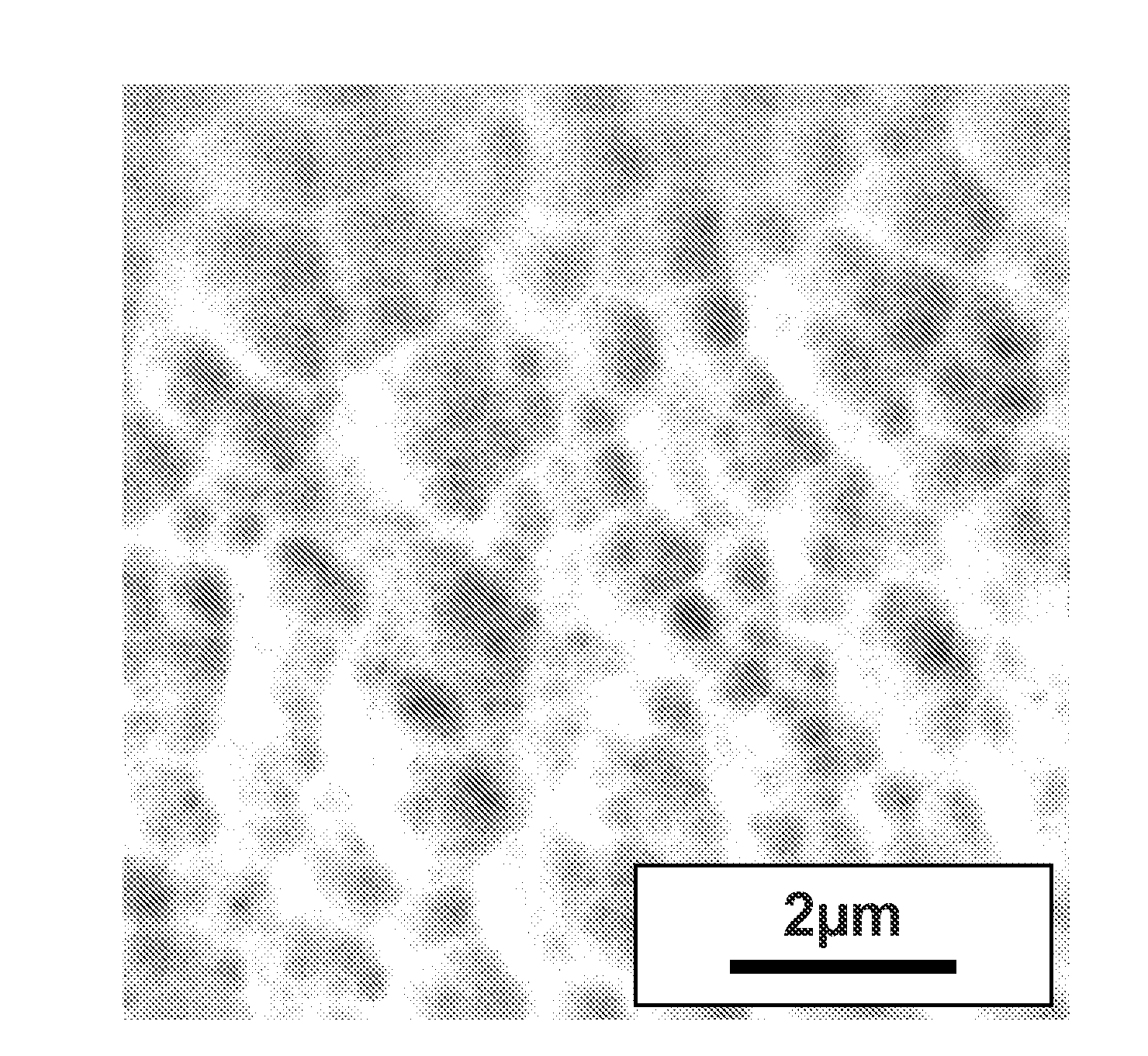
[0074]FIGS. 29, 30 show micrographs from material processed at 873K for 2 hours within a magnetic field of 9 T. Comparison with FIG. 27 shows clear differences in microstructure induced by the field, and demonstrate the elongated morphology of the precipitates induced by the field. The magnetic field processed sample has precipitates that are non-spherical and not uniformly distributed through the sample.
[0075]Comparison between FIGS. 29 and 30 shows the dependence of the developed microstructure on the direction of the applied field, indicated by the arrows in the figure. This demonstrates anisotropic properties developed during heat treatment of the materials in a magnetic field. These results show that microstructural tuning is achievable by combining heat and magnetic field processing.
[0076]The methods and materials described hereinabove can be extended to Hf / Zr—Co—B alloys to make suitable materials for rare-earth free permanent magnets.
[0077]Zirconium has been substituted for ...
PUM
| Property | Measurement | Unit |
|---|---|---|
| Temperature | aaaaa | aaaaa |
| Magnetic field | aaaaa | aaaaa |
| Temperature | aaaaa | aaaaa |
Abstract
Description
Claims
Application Information
 - R&D
- Intellectual Property
- Life Sciences
- Materials
- Tech Scout
- Unparalleled Data Quality
- Higher Quality Content
- 60% Fewer Hallucinations
Browse by: Latest US Patents, China's latest patents, Technical Efficacy Thesaurus, Application Domain, Technology Topic, Popular Technical Reports.
© 2025 PatSnap. All rights reserved.Legal|Privacy policy|Modern Slavery Act Transparency Statement|Sitemap|About US| Contact US: help@patsnap.com


