
Insertion tool

Inactive Publication Date: 2014-04-10
STRAUMANN HLDG AG
View PDF5 Cites 6 Cited by
  • Summary
  • Abstract
  • Description
  • Claims
  • Application Information

AI Technical Summary

Benefits of technology

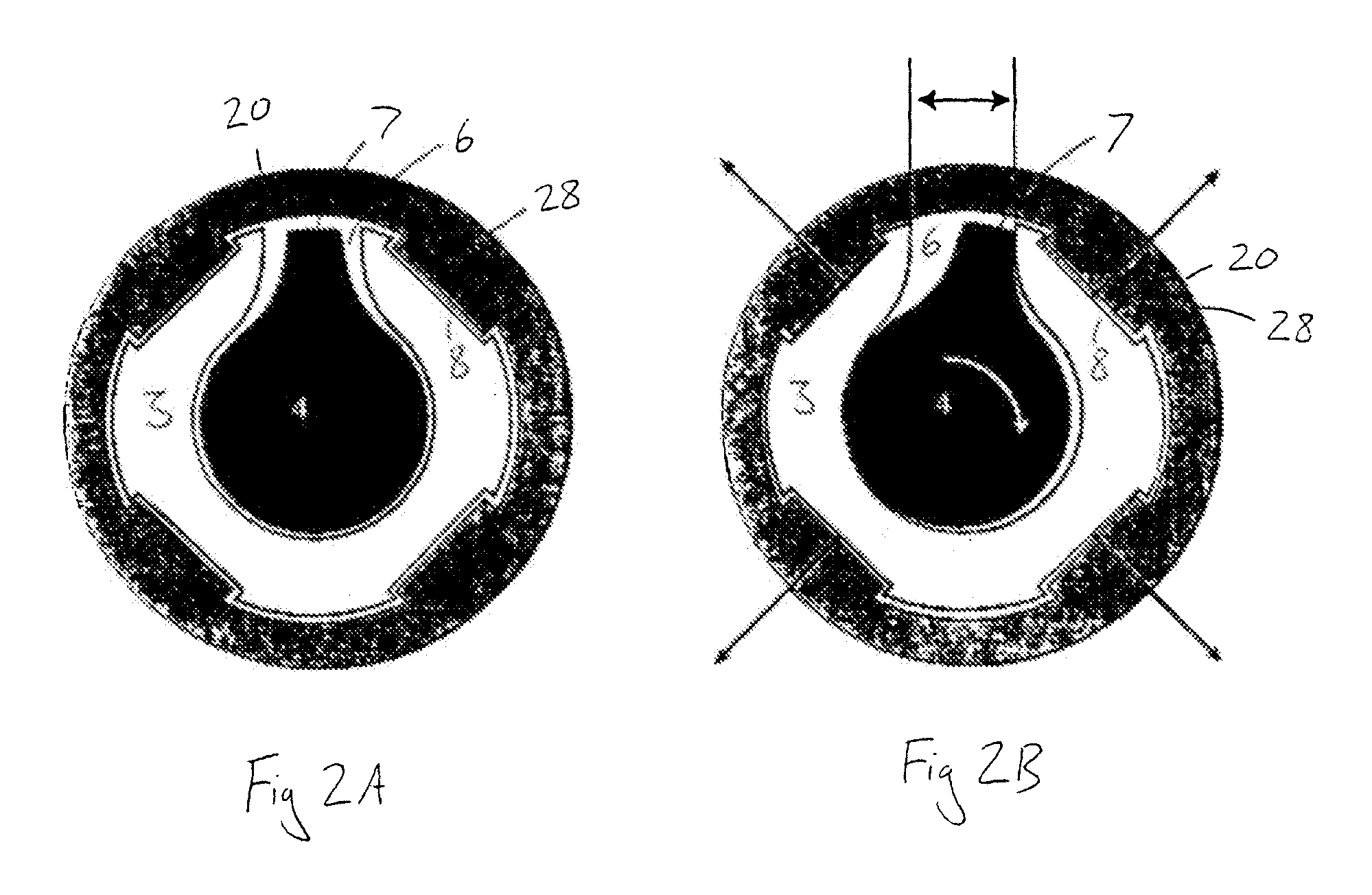
The present invention provides an insertion tool for dental implants that can be adjusted to improve torque transmission between the implant and the tool. The tool features a resilient sleeve that can be expanded or compressed to change its position. When the sleeve is in the second position, it better contacts the anti-rotation surface of the implant, allowing for better torque transmission. The tool can be easily aligned with the implant and then adjusted to improve fit. The tool does not require a separate actuation member and can automatically return to its original position when the actuation force is removed.

Problems solved by technology

In any system, manufacturing tolerances mean that an exact fit between the implant and insertion tool is not possible.
This concentrates the applied force over a small area and can lead to local deformation of both the implant and insertion tool.
As a result, the insertion tool can get jammed within or over the implant, making separation difficult.
In addition, since the anti-rotation means of the implant is often later used to rotationally fix an abutment or prosthesis relative to the implant, deformation of the implant's anti-rotation means can lead to increased rotational play between the implant and the abutment.

Method used


Image

  • Insertion tool
  • Insertion tool
  • Insertion tool

Examples


Embodiment Construction

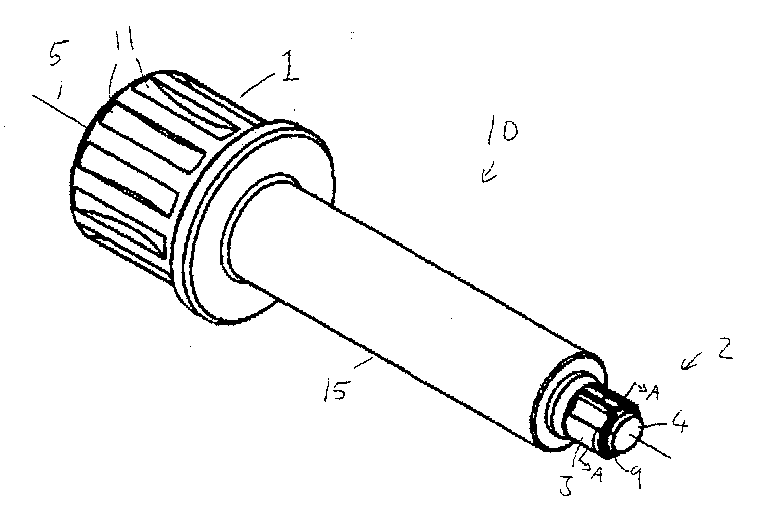
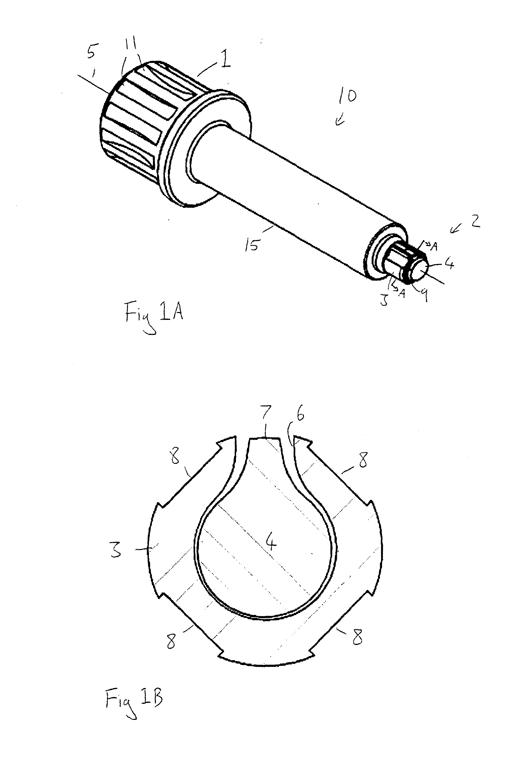
[0079]FIG. 1A shows a perspective view of an insertion tool 10 in accordance with the present invention. The insertion tool 10 extends along a longitudinal axis 5. At its proximal end the tool comprises a driven means in the form of a handle 1. This can be connected to a ratchet or rotated by hand to supply torque to the insertion tool 1. A plurality of longitudinal grooves 11 on the handle 1 interact with a ratchet or provide a good gripping surface for the user. In other embodiments the proximal end may comprise a latch or other non-circular portion for connection to a dental handpiece or other motorised drive device. The handle 1 is integral with the main body 15 of the tool 10 which extends along the longitudinal axis 5. At its distal end the insertion tool 1 comprises a torque transmission means 2. In the present embodiment this takes the form of a resilient sleeve 3 which is attached to the outside of cam shaft 4, this shaft being integral with the main body 15 of the tool 10....


PUM


Abstract

Insertion tool for co-operation with a dental implant, said implant having at least one anti-rotation surface, the insertion tool extending along a longitudinal axis and having at its distal end a resilient sleeve, said sleeve having at least one torque transmission surface and being adjustable between a first, rest position, and a second, stressed position, wherein the location of the at least one torque transmission surface is different in the first and second positions, the insertion tool further including an actuation means arranged to selectively engage with the sleeve in order to adjust the sleeve between the first and second positions, the tool being arranged such that, in use, adjustment of the sleeve from the first to second position enables a better contact between the at least one anti-rotation surface and the at least one torque transmission surface.

Description

FIELD OF THE INVENTION[0001]The present invention relates to an insertion tool for inserting a dental implant into the bone of a patient.BACKGROUND[0002]Dental implants are used to replace individual teeth or for anchoring more complex structures, which generally replace several or even all of the teeth. Many dental implants are initially fastened into the bone of a patient using external threads on the implant body. This provides the implant with primary stability during the osseointegration process.[0003]In general, an insertion tool (or transfer piece) is used to screw the implant into the prepared implant site. This tool must engage with the implant in a way which enables torque to be transmitted from the tool to the implant.[0004]In many implant systems the main bulk of torque transfer occurs via a geometrical fit between the implant and the insertion tool.[0005]In such systems, the implant comprises either an internal or external anti-rotation means. This has a non-circular cr...

Claims


Application Information

Patent Timeline
IPC IPC(8): A61C8/00
CPCA61C8/0089
Inventor COURVOISIER, STEPHANEGUSTAFSSON, EMILIAFAORO, FRANCISCO
Owner STRAUMANN HLDG AG
Learn More