Air conditioner for vehicle

a technology for air conditioners and vehicles, applied in the direction of machines/engines, process and machine control, instruments, etc., can solve the problems of vehicle occupants feeling unwarmed, and achieve the effects of reducing the power consumption of the blower, reducing the availability factor, and saving power

Inactive Publication Date: 2014-04-17
TOYOTA JIDOSHA KK
View PDF4 Cites 16 Cited by
  • Summary
  • Abstract
  • Description
  • Claims
  • Application Information

AI Technical Summary

Benefits of technology

[0009]According to a third aspect of the present invention, there is provided the air conditioner as described in the second aspect, wherein the control device causes the blower to operate at a lower availability factor when the power saving request signal is output than when the power saving request signal is not output.
[0010]Consequently, when power saving is requested by the intention of the occupant, power saving can be achieved by reducing the power consumption of the blower. This makes it possible to not only increase the air flow rate in accordance with the intention of the occupant, but also achieve power saving in accordance with the intention of the occupant.

Problems solved by technology

This inhibits an occupant of the vehicle from feeling unwarmed as the blower blows insufficiently heated air to the feet of the occupant if the engine cooling water temperature is low when, for instance, a heater is started.

Method used


Image

  • Air conditioner for vehicle
  • Air conditioner for vehicle
  • Air conditioner for vehicle

Examples


first embodiment

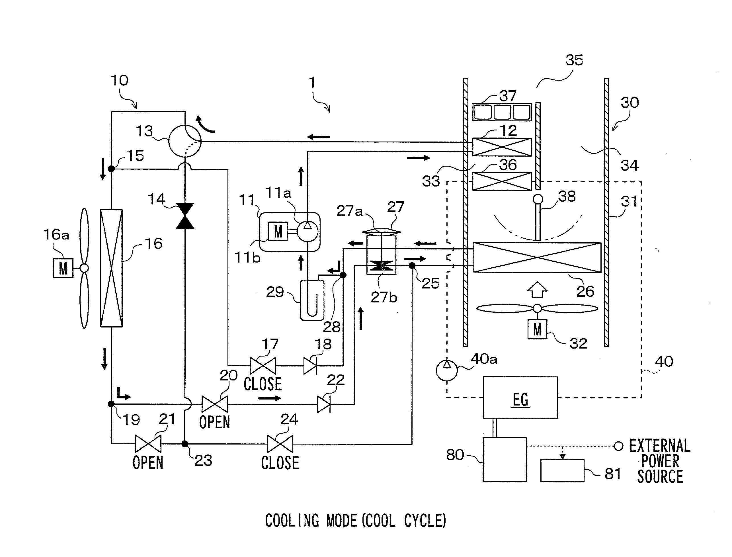
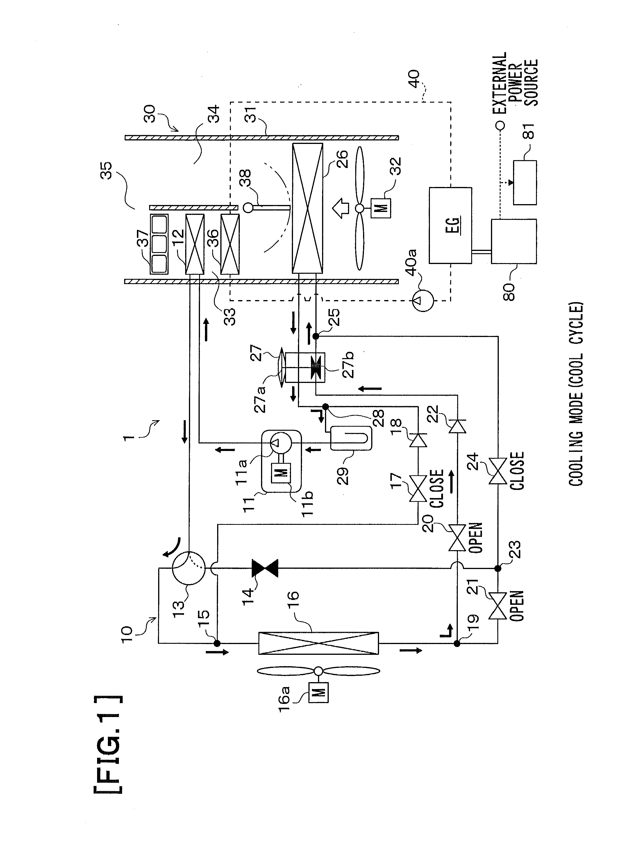
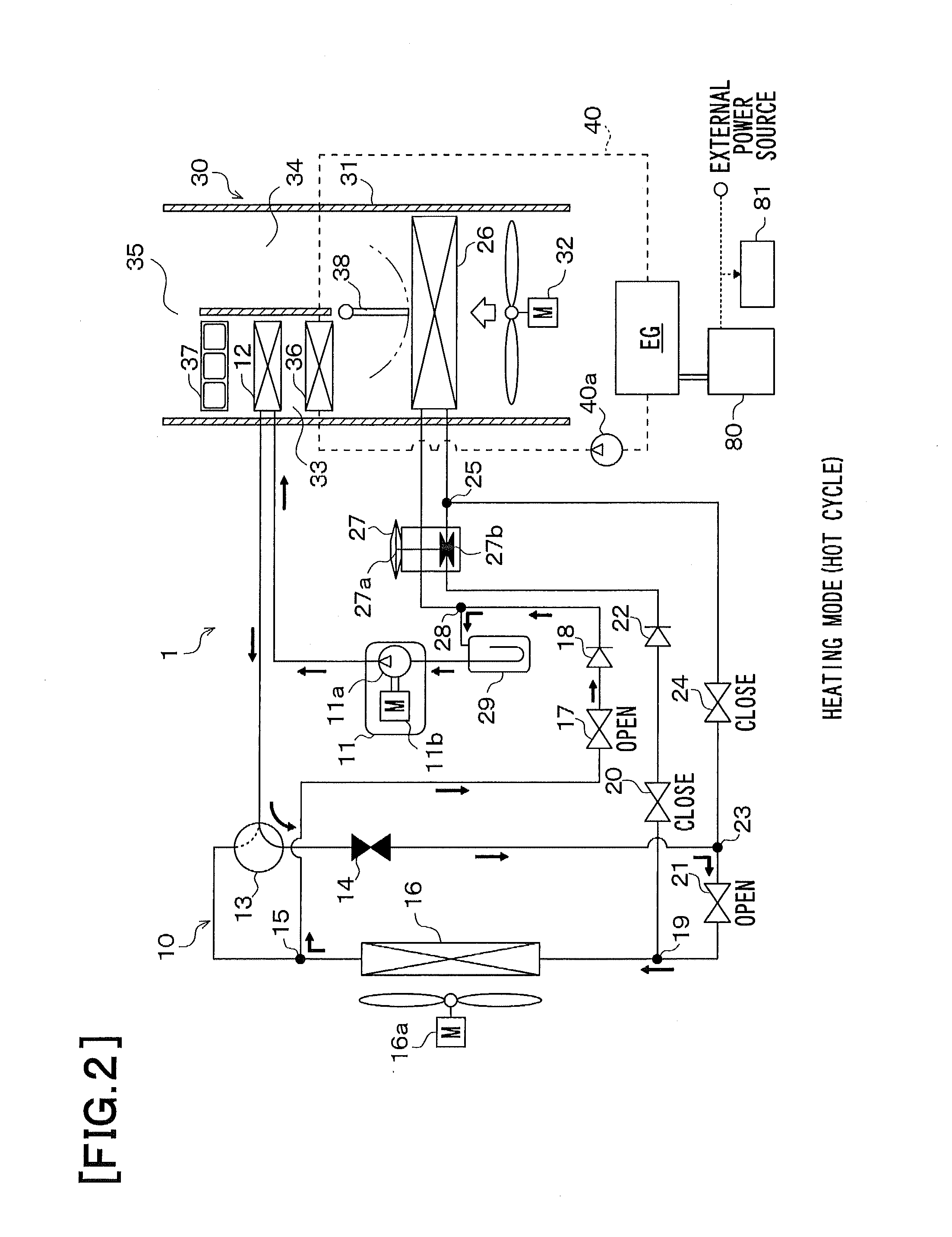
[0026]A first embodiment of the present invention will now be described with reference to FIGS. 1 to 11. FIGS. 1 to 4 are diagrams illustrating the overall configuration of an air conditioner for a vehicle according to the first embodiment. FIG. 5 is a block diagram illustrating an electrical control section of the air conditioner for a vehicle 1. In the present embodiment, the air conditioner for a vehicle is applied to a hybrid vehicle that acquires a driving force for running the vehicle from an internal combustion engine EG and from a driving electric motor.

[0027]The hybrid vehicle according to the present embodiment is a so-called plug-in hybrid vehicle capable of charging its battery 81 with electricity supplied from an external power source (commercial power source) while the vehicle is stopped. If the battery 81 is charged by the external power source while the vehicle is stopped before running so that the amount of electrical power remaining in the battery 81 is not smaller...

second embodiment

[0194]A second embodiment of the present invention will now be described with reference to FIG. 12. The second embodiment is obtained by modifying the control aspect of the blower 32 according to the first embodiment, which is described earlier.

[0195]The control aspect of the blower 32 according to the second embodiment will be described below with reference to FIG. 12. FIG. 12 is a flowchart illustrating a control process that corresponds to the control process shown in FIG. 8, which depicts the first embodiment. First of all, step S721 is performed to determine whether the auto switch on the operation panel 60 is turned on, as is the case with the first embodiment. If the determination result obtained in step S721 does not indicate that the auto switch is turned on, processing proceeds to step S722. Step S722 is performed to determine the blower motor voltage that provides an air flow rate desired by the occupant, which is set by the air flow rate setup switch on the operation pan...

third embodiment

[0246]The refrigeration cycle 10 employed in the foregoing embodiments is configured so that the refrigerant circuits for the cooling mode, the heating mode, the first dehumidification mode, and the second dehumidification mode can be selectively used. However, the refrigeration cycle 10 used in a third embodiment of the present invention does not have a function for selecting various refrigerant circuits, as shown in FIG. 13.

[0247]More specifically, the refrigeration cycle 10 according to the third embodiment is formed by circularly connecting the compressor 11, the outdoor heat exchanger 16, the thermostatic expansion valve 27, and the indoor evaporator 26 in the order named. The refrigeration cycle 10 according to the present embodiment functions to cool the air to be blown into the passenger compartment from the blower. In other words, the refrigeration cycle 10 according to the present embodiment is configured to be capable of providing the cooling mode of the foregoing embodim...


PUM


Abstract

An air conditioner for a vehicle includes a blower that generates blown air; a heating heat exchanger that heats the blown air by heat exchange between the blown air and a heat medium; a target temperature setup device that sets a target temperature for a passenger compartment in accordance with an operation performed by an occupant; and a control device that determines the availability factor of the blower in accordance with the temperature of the heat medium wherein the control device increases the availability factor of the blower as the target temperature increases.

Description

TECHNICAL FIELD[0001]The present invention relates to an air conditioner for a vehicle.BACKGROUND ART[0002]In a conventional air conditioner for a vehicle, control is exercised to stop a blower when an engine cooling water temperature is not higher than a predetermined temperature, start the blower when the engine cooling water temperature is higher than the predetermined temperature, and increase the amount of air blown from the blower when the engine cooling water temperature rises (refer, for instance, to PTL 1). This inhibits an occupant of the vehicle from feeling unwarmed as the blower blows insufficiently heated air to the feet of the occupant if the engine cooling water temperature is low when, for instance, a heater is started.CITATION LISTPatent Literature[PTL 1]Japanese Patent Application Publication No. 2769073SUMMARY OF INVENTIONTechnical Problem[0003]However, when the invention described in PTL 1 is employed, the temperature of the engine cooling water (a heat medium f...

Claims


Application Information

Patent Timeline
Patent Type & Authority Applications(United States)
IPC IPC(8): F01P7/02
CPCF01P7/026B60H1/00828B60H1/00921
Inventor ICHISHI, YOSHINORITAKEUCHI, TETSUYAHIRABAYASHI, HIDEKAZUSHIMADA, YOSHIHISA
Owner TOYOTA JIDOSHA KK
Why Eureka
Try Eureka