Thermostatically-Controlled Multi-Mode Coolant Loops

Active Publication Date: 2014-04-17
FORD GLOBAL TECH LLC
View PDF17 Cites 53 Cited by
  • Summary
  • Abstract
  • Description
  • Claims
  • Application Information

AI Technical Summary

Benefits of technology

[0007]The heat transfer system of the present invention employs a multi-way (e.g., two-position three-way) mechanical thermostatic diverter valve and in some embodiments a check valve in a manner that avoids the need for electronic controllers or actuators. The vehicle prime energy source can be a combustion engine or fuel cell, for example. The auxiliary heating device can be a fuel operated heater, positive temperature coefficient (PTC) coolant heater, or exhaust heat recovery system. The coolant circuit operates in a mixed loop mode configured such that coolant flows in a common circuit including the prime energy source and pump, auxiliary heating device, and the cabin heat exchanger. An isolated loop mode is configured such that coolant flow is separated into two circuits by th

Problems solved by technology

Modern energy-efficient vehicles such as battery electric, hybrid, fuel cell, diesel

Method used


Image

  • Thermostatically-Controlled Multi-Mode Coolant Loops
  • Thermostatically-Controlled Multi-Mode Coolant Loops
  • Thermostatically-Controlled Multi-Mode Coolant Loops

Examples


first embodiment

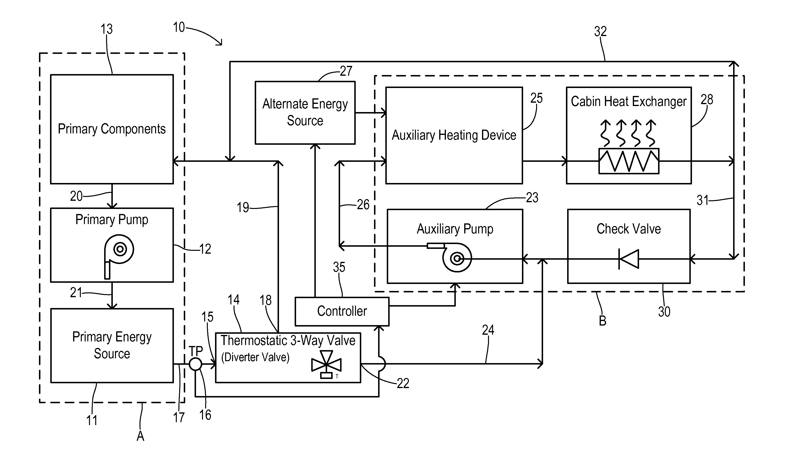
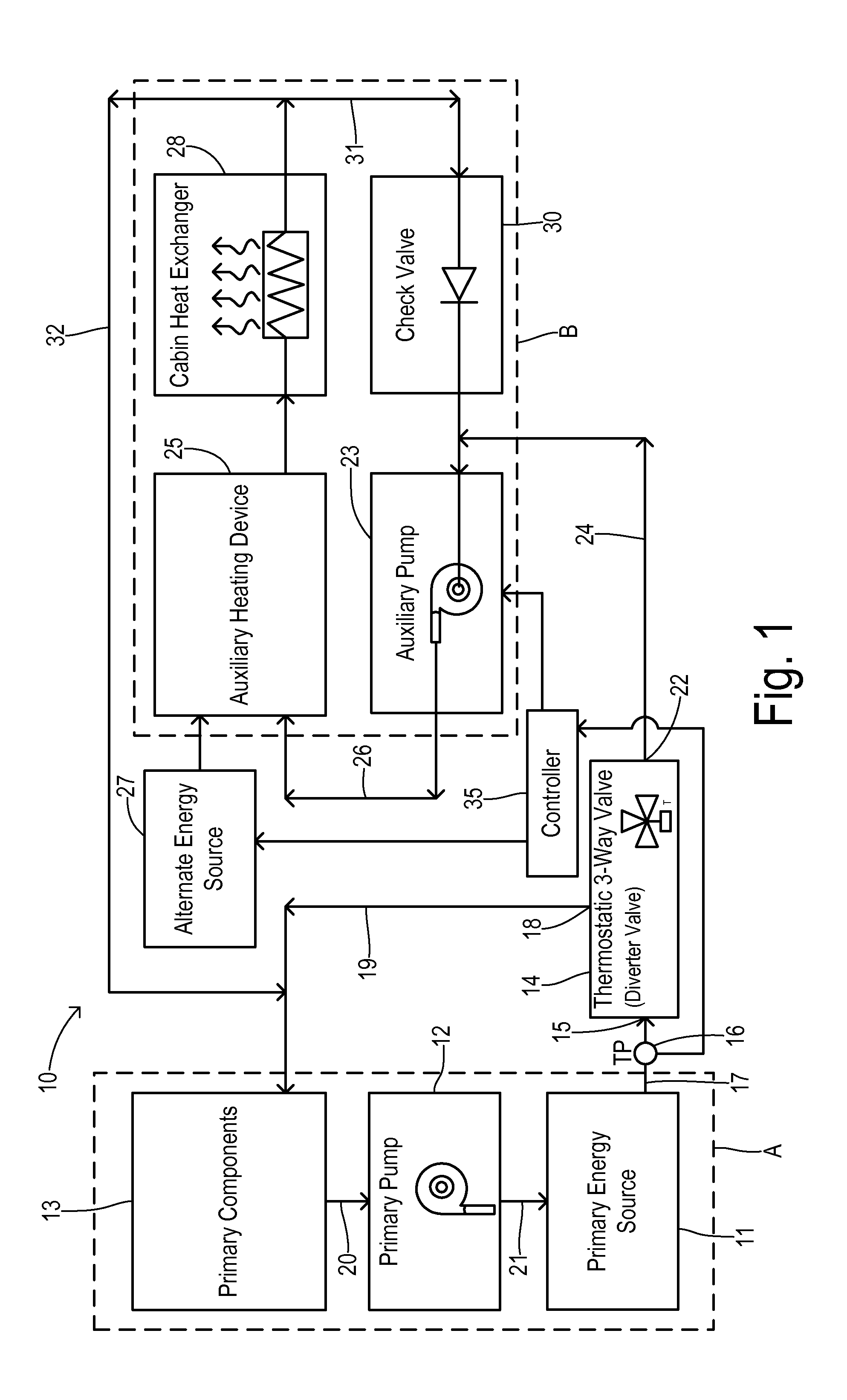
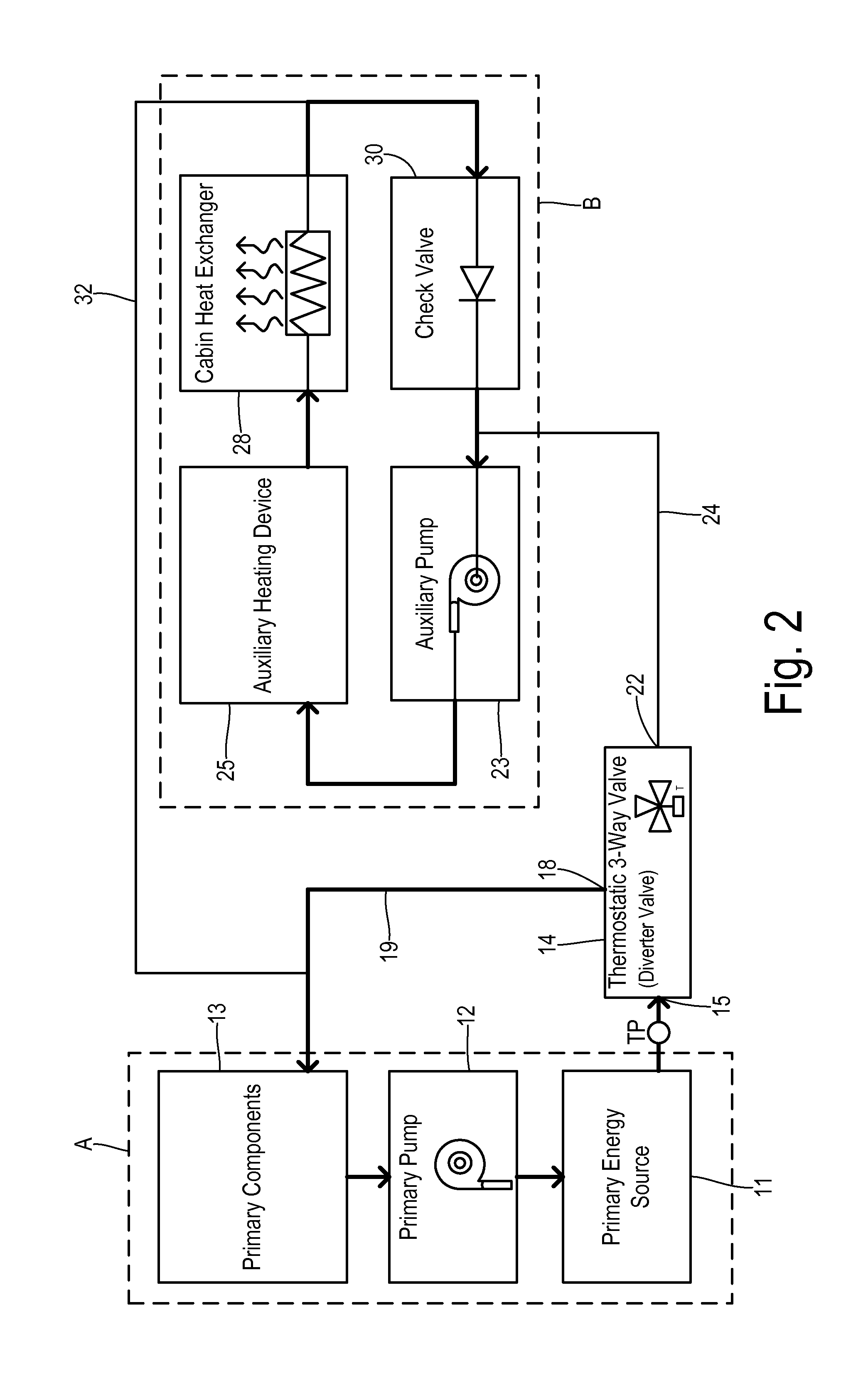
[0025]FIG. 2 shows operation of this first embodiment in an isolated loops mode that occurs when primary energy source 11 insufficiently heats the coolant. Thermostatic valve 14 is configured to direct coolant from inlet 15 to substantially only first outlet 18 when the coolant received at inlet 15 is below a first setpoint temperature. On the other hand, valve 14 directs coolant from inlet 15 to substantially only second valve outlet 22 when receiving coolant at inlet 15 having a temperature TP that is at or above a second setpoint temperature which is higher than the first setpoint temperature. The first and second setpoint temperatures are determined according to the mechanical properties of valve 14 which may be of conventional construction (e.g., based on wax or another phase-change material). A heavier line weight for the coolant conduits in FIG. 2 identifies portions of the coolant circuit where coolant flows during the isolated loop mode. Thus, thermostatic valve 14 is set t...

second embodiment

[0030]Operation of the second embodiment shown in FIGS. 4-6 is as follows. Starting with cold coolant, valve 14 is positioned to result in the isolated (dual) loops mode (FIG. 5) to provide rapid warming of the passenger cabin via auxiliary heating device 25. No flow occurs between branches A and B via conduit 44 because of the conservation of mass and because conduit 45 is blocked at second outlet 22 of valve 14. When coolant temperature TA of the auxiliary branch B entering valve 14 increases above the first setpoint temperature, valve 14 gradually changes position until the second setpoint temperature is reached. At that point, valve 14 is in a position to divert substantially all of the coolant flow into the mixed loop (single loop) mode which shares coolant heated by primary energy source 11 to both branches A and B. Advantages of the embodiment shown in FIGS. 4-6 include achieving a faster peak efficiency of primary energy source 11 as well as the other components in primary b...


PUM


Abstract

A heat transfer system is provided for a road vehicle having a passenger cabin. A primary branch includes a primary pump and a primary power plant. An auxiliary branch includes an auxiliary coolant pump, an auxiliary heat source, and a cabin heat exchanger. A thermostatic multi-way valve directs coolant from a valve inlet to substantially only a first valve outlet when receiving coolant below a first temperature. The valve directs coolant from the valve inlet to substantially only a second valve outlet when receiving coolant above a second temperature. The valve inlet is coupled to receive coolant from either the primary branch or the auxiliary branch. The first valve outlet is configured to return coolant to the same branch as is connected to the valve inlet. The second valve outlet is configured to direct coolant to the other branch to which the valve inlet is not connected.

Description

CROSS REFERENCE TO RELATED APPLICATIONS[0001]Not Applicable.STATEMENT REGARDING FEDERALLY SPONSORED RESEARCH[0002]Not Applicable.BACKGROUND OF THE INVENTION[0003]The present invention relates in general to an integrated engine cooling and cabin heating system for transportation vehicles, and, more specifically, to a method and apparatus for circulating coolant.[0004]Historically, transportation vehicles powered by combustion engines have produced sufficient waste heat from the combustion to supply all the needed heat for warming the passenger cabin during cold weather. Considering regulations and marketplace demand for higher fuel economy and lower emissions, the global automotive market is rapidly evolving to require alternative fuel vehicles and higher efficiency (lower waste heat) engines. Modern energy-efficient vehicles such as battery electric, hybrid, fuel cell, diesel engine, small displacement petrol engine vehicles pose challenges for cabin heating. In many cases an auxili...

Claims


Application Information

Patent Timeline
IPC IPC(8): B60H1/03G05D23/02B60H1/20
CPCB60H1/00885B60H1/143F01P3/20F01P2060/08
Inventor PATEL, UPENDRA J.MADHAVAN, RANGANATHAN
Owner FORD GLOBAL TECH LLC
Why Eureka
Try Eureka