
Control channel for wireless communication

a control channel and wireless communication technology, applied in the field of wireless communication systems, can solve the problems of large overhead of pdcch payload, less optimal machine-to-machine, machine-to-human, or human-to-machine applications, etc., and achieve the effect of reducing the additional decoding effort and increasing the number of pdch messages

Active Publication Date: 2014-04-17
FUJITSU LTD
View PDF14 Cites 106 Cited by
  • Summary
  • Abstract
  • Description
  • Claims
  • Application Information

AI Technical Summary

Benefits of technology

The patent describes a method for efficiently transmitting information in a control signal using a predefined format. This format allows the use of a small number of bits to set values of multiple parameters simultaneously, which can save time and resources. The method also reduces the amount of additional decoding required at terminals and allows for more PDCH messages to be transmitted. The control signals are transmitted within a common search space or a distinct search space, depending on the needs of the system. Overall, this method improves the efficiency and flexibility of the control signal transmission.

Problems solved by technology

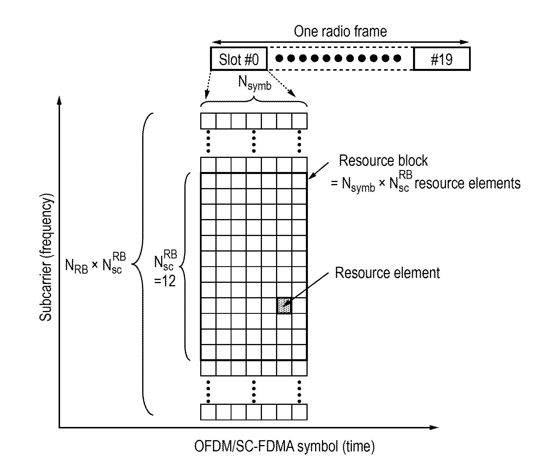
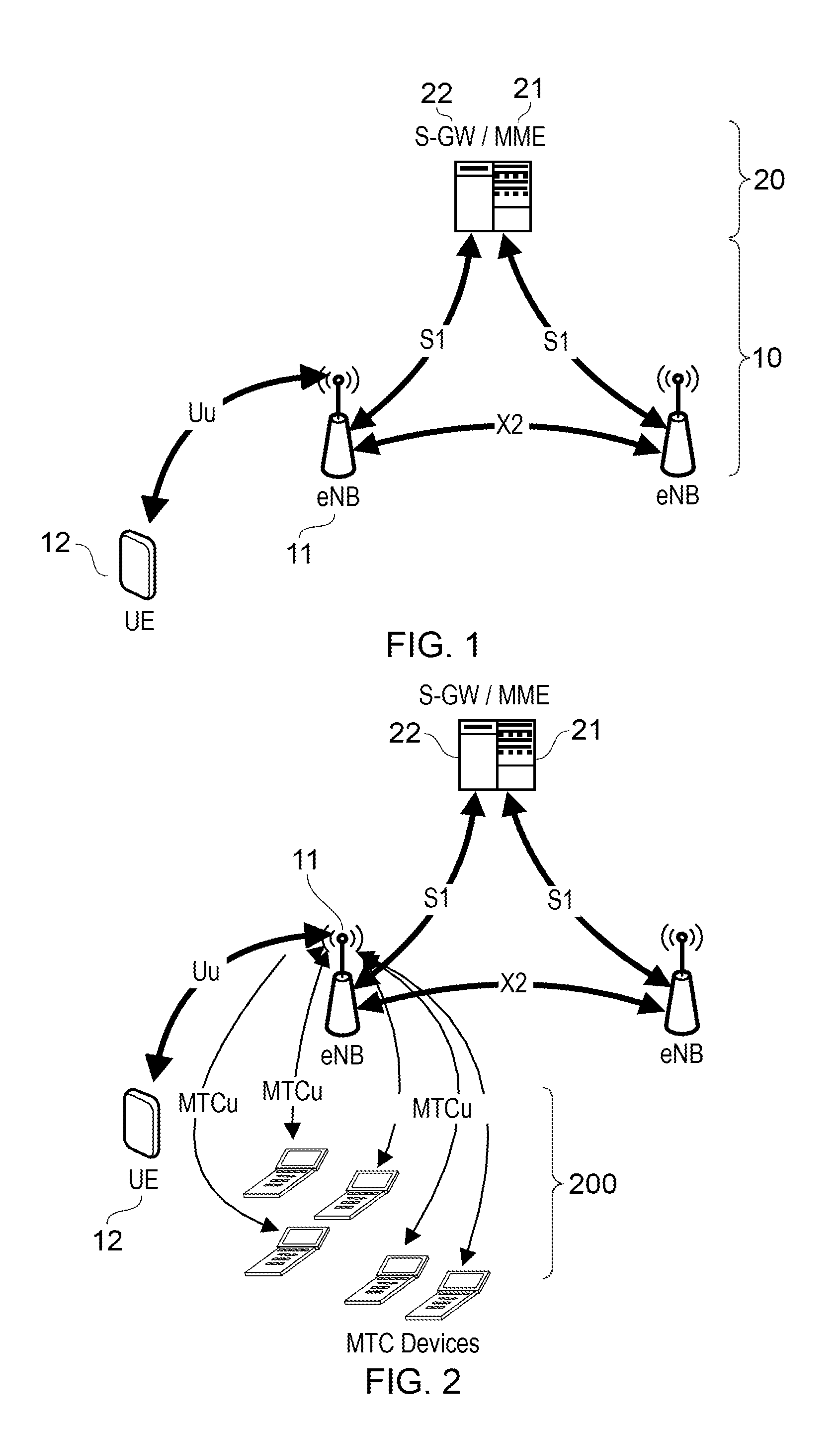
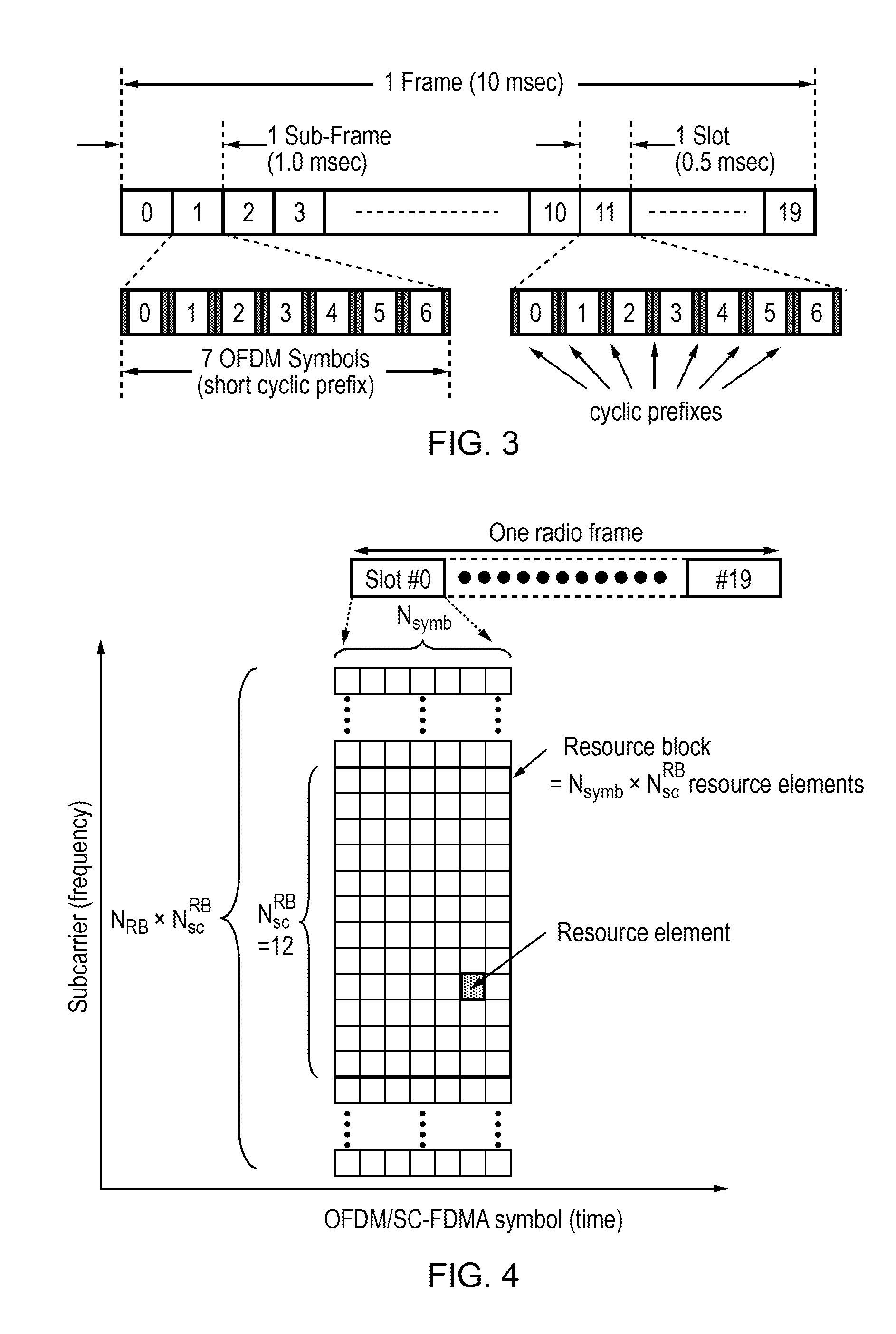
Modern wireless communication systems such as LTE and LTE-A are hugely complex and a full description of their operation is beyond the scope of this specification.
Current mobile networks are optimally designed for Human-to-Human communications, but are less optimal for machine-to-machine, machine-to-human, or human-to-machine applications.
For some applications only small data packets are required, so the PDCCH payload may represent a significant overhead.
In addition, there is a limit on the maximum number of PDCCH messages that can be transmitted at the same time (i.e. within the same subframe), which may be insufficient to support a large number of active UEs transmitting or receiving only small data packets.

Method used


Image

  • Control channel for wireless communication
  • Control channel for wireless communication
  • Control channel for wireless communication

Examples


first embodiment

[0159]In a first embodiment based on LTE, the network operates using FDD and comprises one or more eNBs, each controlling at least one downlink cell, each downlink cell having a corresponding uplink cell. Each DL cell may serve one or more terminals (UEs) which may receive and decode signals transmitted in that cell. In order to schedule the appropriate use of transmission resources in time, frequency and spatial domains for transmission to and from the UEs, the eNBs send control channel messages (PDCCH) to the UEs.

[0160]As already mentioned, a PDCCH message typically indicates whether the data transmission will be in the uplink (using PUSCH) or downlink (using PDSCH), it also indicates the transmission resources, and other information such as transmission mode and data rate. The UE performs blind decoding for a number of possible PDCCH message types (DCI formats) over a defined search space on the downlink primary cell (Pcell). A given UE is configured by higher layer signalling (e...

second embodiment

[0209]A second embodiment is similar to the first embodiment except that a given DCI bit is used to convey information to more than one UE simultaneously. The interpretation of the information bit may be the same or different for different UEs, for example corresponding to different RRC configurations of UL and / or DL assignments. A group of UEs is defined by configuring them with the same value of DCI-BIT-RNTI.

[0210]In a preferred version of this second embodiment, format 3B is used to convey the same command to a number of UEs. For example:—[0211]Change of state (e.g. to idle mode or “off” state)[0212]Request to transmit data (e.g. one or more sensor measurements or meter readings)[0213]Change in application level data (e.g. change in electricity tariff, in the case of an electricity meter).

[0214]In this instance, an additional / alternative (or possibly extended) search space would be more appropriate. The advantage is that a larger search space makes it possible to transmit more PD...

specific embodiment

SPS

[0216]As a specific embodiment of the present invention, we now consider potential improvement to SPS operation in LTE (i.e. LTE-Advanced) to improve operational flexibility but with low control channel overhead.

[0217]The specific embodiment is intended to be applied to SPS, so that the indicated set of parameter values for a given UE is applied to the operation of SPS for that UE. For example this can be achieved by modification of the parameters applying to a single transmission scheduled according to SPS, or modification of the parameters to be applied subsequently.

[0218]In this case, the new Format 3B already outlined above is modified as follows: If a UE is configured by higher layers to decode PDCCHs with the CRC scrambled by the SPSG C-RNTI, the UE shall decode the PDCCH according to the combination defined in table 8.9.

TABLE 8-9PDCCH configured by SPSG C--RNTIDCI formatSearch SpaceDCI format 3BCommon

[0219]The SPSG C-RNTI is a new RNTI indicating a group of UEs configured ...


PUM


Abstract

A scheme for transmission of control channel information in a compact form intended to support SPS (Semi-Persistent Scheduling) in a wireless communication system. As applied to LTE, the scheme is to indicate a pre-configured UE-specific resource allocation in a Downlink Control Information (DCI) format containing information for multiple UEs in the same PDCCH. In order to avoid increasing the number of blind decodes, the DCI format size may be the same as an existing DCI format. Preferably the size of the new format is the same as that of DCI formats 0 / 1A / 3 / 3A. The number of required bits per UE is minimised by signalling only one of a limited set of DCI messages per UE. The scheme provides a means for re-configuring SPS resources for multiple UEs using a single PDCCH transmission, whilst enabling better support for variable packet sizes and variable intervals between packets than currently defined SPS.

Description

CROSS-REFERENCE TO RELATED APPLICATIONS[0001]This is a continuation of international Application No. PCT / EP2011 / 069444, filed Nov. 4, 2011, which claims priority from international Application No. PCT / EP2011 / 063164, filed Jul. 29, 2011, now pending, the contents of which are herein wholly incorporated by reference.FIELD OF THE INVENTION[0002]The present invention relates to wireless communication systems, for example systems based on the 3GPP Long Term Evolution (LTE) and 3GPP LTE-A groups of standards.BACKGROUND OF THE INVENTION[0003]Wireless communication systems are widely known in which base stations (BSs) form “cells” and communicate with user equipments (UEs) (also called subscriber or mobile stations) within range of the BSs.[0004]In such a system, each BS divides its available bandwidth, i.e. frequency and time resources in a given cell, into individual resource allocations for the user equipments which it serves. The user equipments are generally mobile and therefore may mo...

Claims


Application Information

Patent Timeline
Patent Type & Authority Applications(United States)
IPC IPC(8): H04W72/04H04W4/70
CPCH04W72/042H04W28/18H04L5/003H04W4/70H04W72/23H04B7/2603H04J11/0069H04W72/21H04L5/0007H04L27/2614H04W72/0446
Inventor MOULSLEY, TIMOTHYTESANOVIC, MILOS
Owner FUJITSU LTD
Learn More