Piping system from reactor to separator and method to control process flow

Inactive Publication Date: 2014-04-24
ANDRITZ INC
View PDF7 Cites 8 Cited by
  • Summary
  • Abstract
  • Description
  • Claims
  • Application Information

AI Technical Summary

Benefits of technology

The patent is about ways to prevent obstructions in piping systems, which can be caused by biomass deposits. One solution is to shorten the distance between the reactor vessel and the separation device, which reduces the surface area and edges on which biomass can catch. However, this may not always be possible due to space limitations. The patent proposes a solution to this problem, which can allow for a longer distance between the reactor vessel and separation device while still reducing the likelihood of obstructions.

Problems solved by technology

Small pipe diameters may help accomplish this goal but unfortunately, these small diameters also contribute to blockage.
These partially opened valves may present valve edges within the pipes that are prone to catching deposits of biomass material.
As these biomass deposits accumulate, the pipes become plugged, blocked, or obstructed.
Further, flow velocities approaching the speed of sound are typical in systems that operate with a high pressure drop from the reactor to the separation device.
As a result, the valves and other movable parts within the piping systems can wear out frequently requiring repair or replacement.
The diameter of the piping may also be increased, but this may require an increased quantity of steam usage.
Space limitations and other equipment can impose difficulties in proximally locating a reactor vessel and separation device.

Method used


Image

  • Piping system from reactor to separator and method to control process flow
  • Piping system from reactor to separator and method to control process flow
  • Piping system from reactor to separator and method to control process flow

Examples


Embodiment Construction

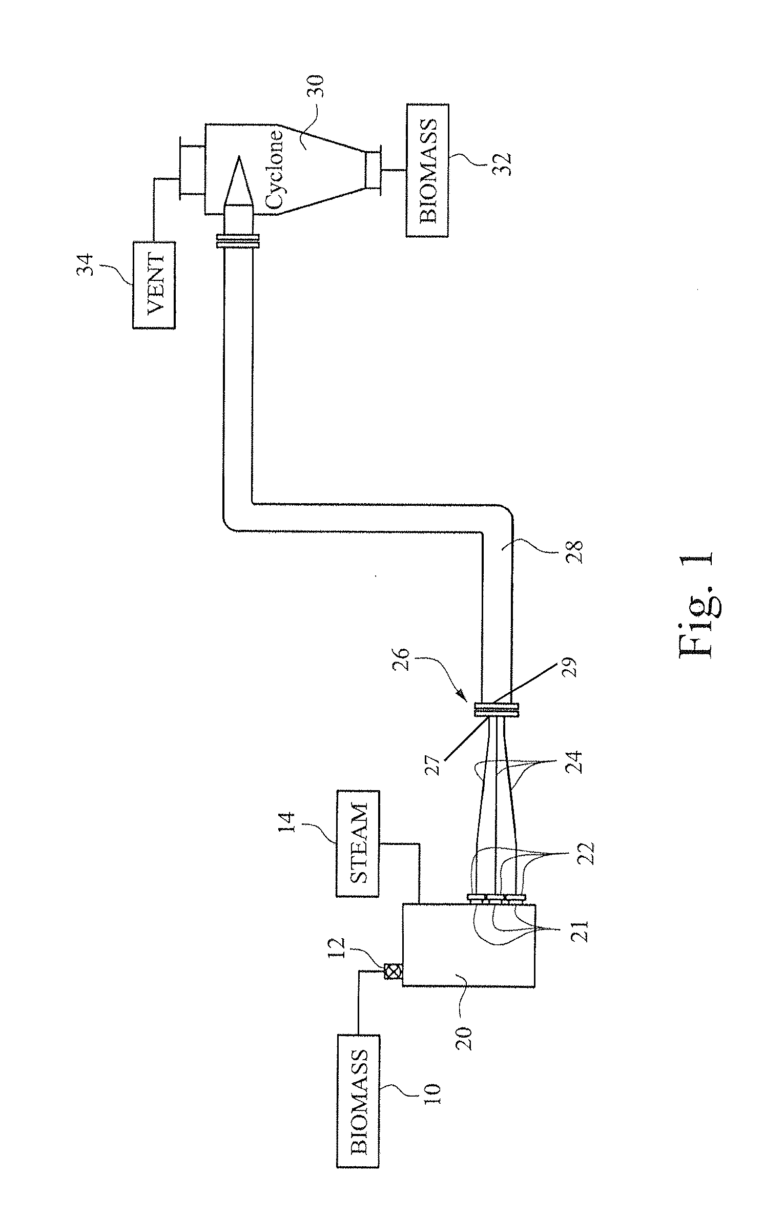
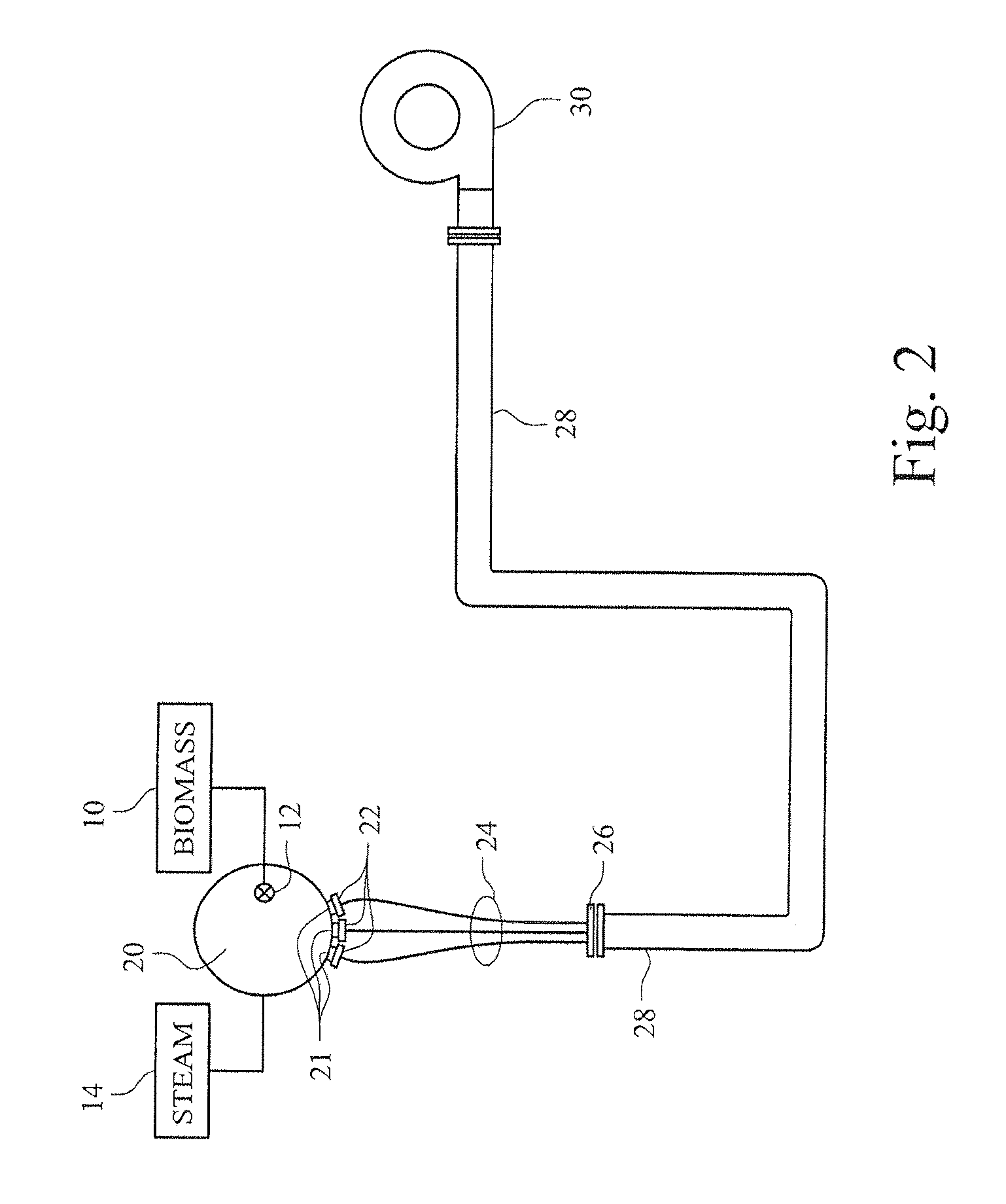
[0025]FIGS. 1 and 2 illustrate a steam explosion process in which pressurized steam is infused into a biomass material, such as lignocellulosic material. By rapidly releasing the pressure, the steam expands within the biomass material and bursts the cells of the biomass material or defibrillates the biomass material. The biomass material may be lignocellulosic material. Lignocellulosic material includes, but is not limited to: plant material such as wood, wood chips, sawmill and paper mill discards, corn stover, sugarcane bagasse, and other agricultural residues, dedicated energy crops, municipal paper waste, and any other biomass material composed of cellulose, hemicellulose, and lignin.

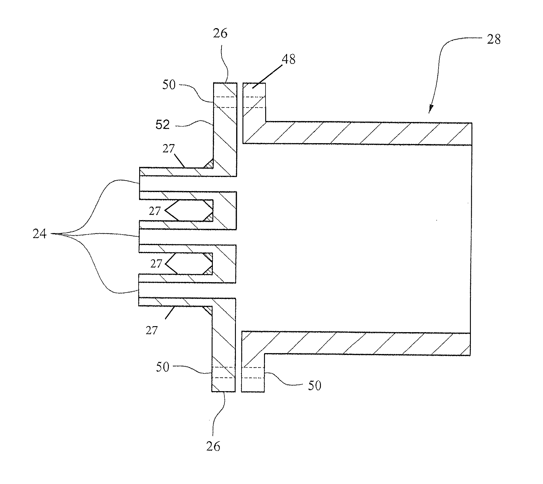
[0026]In this example embodiment of an apparatus for steam explosion treatment, a pressurized reactor vessel 20 receives the biomass material 10 via a high pressure transfer device 12 which conveys the biomass material 10 into a high pressure environment in the pressurized reactor vessel 20. The bio...


PUM


Abstract

An apparatus, for the steam explosion treatment of biomass, having a pressurized reactor vessel to receive a biomass material and steam, discharge lines connecting the pressurized reactor vessel to the separation device, the lines sized and positioned to allow for the steam explosion of biomass material. At the outlet end of the discharge lines is a collection-expansion manifold to connect the outlet end of each of the discharge lines to a collection line, wherein the collection line provides a passage for biomass material and steam flowing from the discharge lines. The collection line passage has a substantially larger cross-sectional area than the cross-sectional area of a single discharge line. The collection line is coupled to a separation device such that the separation device receives the biomass material and steam from the collection line.

Description

CROSS-REFERENCE TO PRIOR APPLICATION[0001]This application claims the benefit of priority to U.S. App. No. 61 / 717,684 filed on Oct. 24, 2012, the entire contents of which are incorporated herein by reference.BACKGROUND OF THE INVENTION[0002]Current steam explosion systems usually consist of a reactor vessel, a piping system, and a separation device. The reactor vessel holds steam-infused biomaterial under pressure. The steam-infused biomass material rapidly depressurizes in the piping system as it is conveyed from the reactor vessel to the separation device. The separation device recaptures steam and other desirable gasses.[0003]The piping systems have traditionally been susceptible to plugging, blocking, or obstruction by the biomass material that flows through them. When obstructed, traditional steam explosion systems are generally shut down for maintenance. This may result in a loss of production. Many piping system features that contribute to this problem.BRIEF DESCRIPTION OF TH...

Claims


Application Information

Patent Timeline
IPC IPC(8): D21B1/12
CPCD21B1/12D21B1/36D21C1/02B01J19/26F17D1/02
Inventor RAWLS, JOSEPH MONROEPSCHORN, THOMASSTROMBERG, BERTILPEPIN, PATRICK
Owner ANDRITZ INC
Why Eureka
Try Eureka