Rotary spray shower head

a rotary spray and shower head technology, applied in the direction of spraying apparatus, spray nozzle, movable spraying apparatus, etc., can solve the problems of large current momentum, poor comfort of taking a shower, and inability to achieve the desired effect, and achieve the effect of simple structure and good rotary spray discharge

Active Publication Date: 2014-04-24
SINYU TECH FUJIAN
View PDF9 Cites 11 Cited by
  • Summary
  • Abstract
  • Description
  • Claims
  • Application Information

AI Technical Summary

Benefits of technology

[0006]The primary object of the present invention is to provide a rotary spray shower head. The structure is simple, the rotating speed can be controlled, and the rotary spray discharge effect is good.
[0014]The present invention has a simple structure. When in use, the water in the main body flows to the water distributing plate to be distributed. One portion of the water flows out from the ordinary discharge openings through the ordinary water holes of the water distributing plate and the rear faceplate to achieve the ordinary discharge function of the spray shower head. Another portion of the water flows to the inclined openings to strike and turn the impeller. The impeller drives the driven gear through the pinion, and then the driven gear brings the water outlet head assembly to turn through the hollow connecting stem. In the meanwhile, the water flows through the power room where the impeller is located, and then flows to the water cavity of the water outlet head assembly through the hollow connecting stem at the shaft hole of the driven gear, and finally sprays out from the water outlet in a rotary manner. The present invention uses the pinion and the driven gear to constitute a planet deceleration. The rotating speed can be controlled, and the rotary spray discharge effect is good.

Problems solved by technology

In particular, in the case of high water pressure, the current momentum is large, and the comfort of taking a shower is poor.
But, the rotation range of each discharge nozzle of this shower head is too small so the area of the rotary water is small, not achieving the desired effect.
This structure is only suitable for small nozzles of the shower head.
If the number of the nozzles increases, the components of the shower head will increase, and the processing and assembly will be difficult and the cost will increase because each nozzle is an independent component.
It is difficult to control the rotational speed.
If the water pressure is too small, it is unable to drive the rotor.
If the water pressure is too big, the speed is too high and the effect is not good.
Especially, when the water pressure is lower, it is difficult to rotate and discharge water.

Method used


Image

  • Rotary spray shower head
  • Rotary spray shower head
  • Rotary spray shower head

Examples


Embodiment Construction

[0026]Embodiments of the present invention will now be described, by way of example only, with reference to the accompanying drawings.

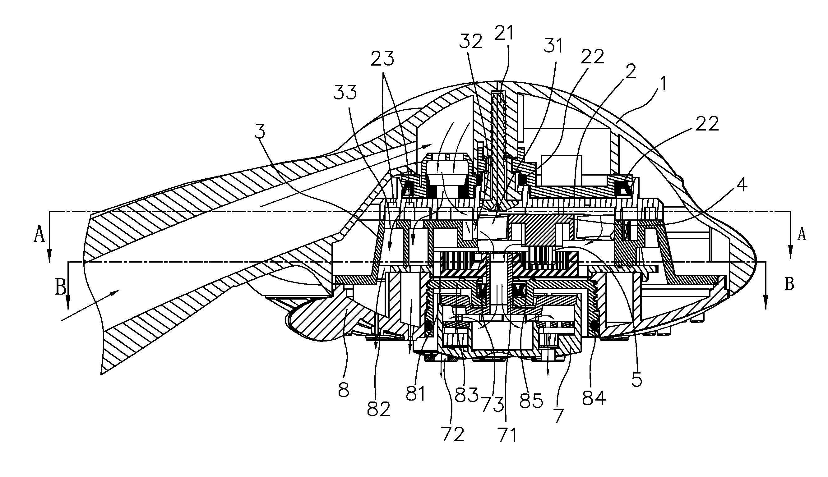
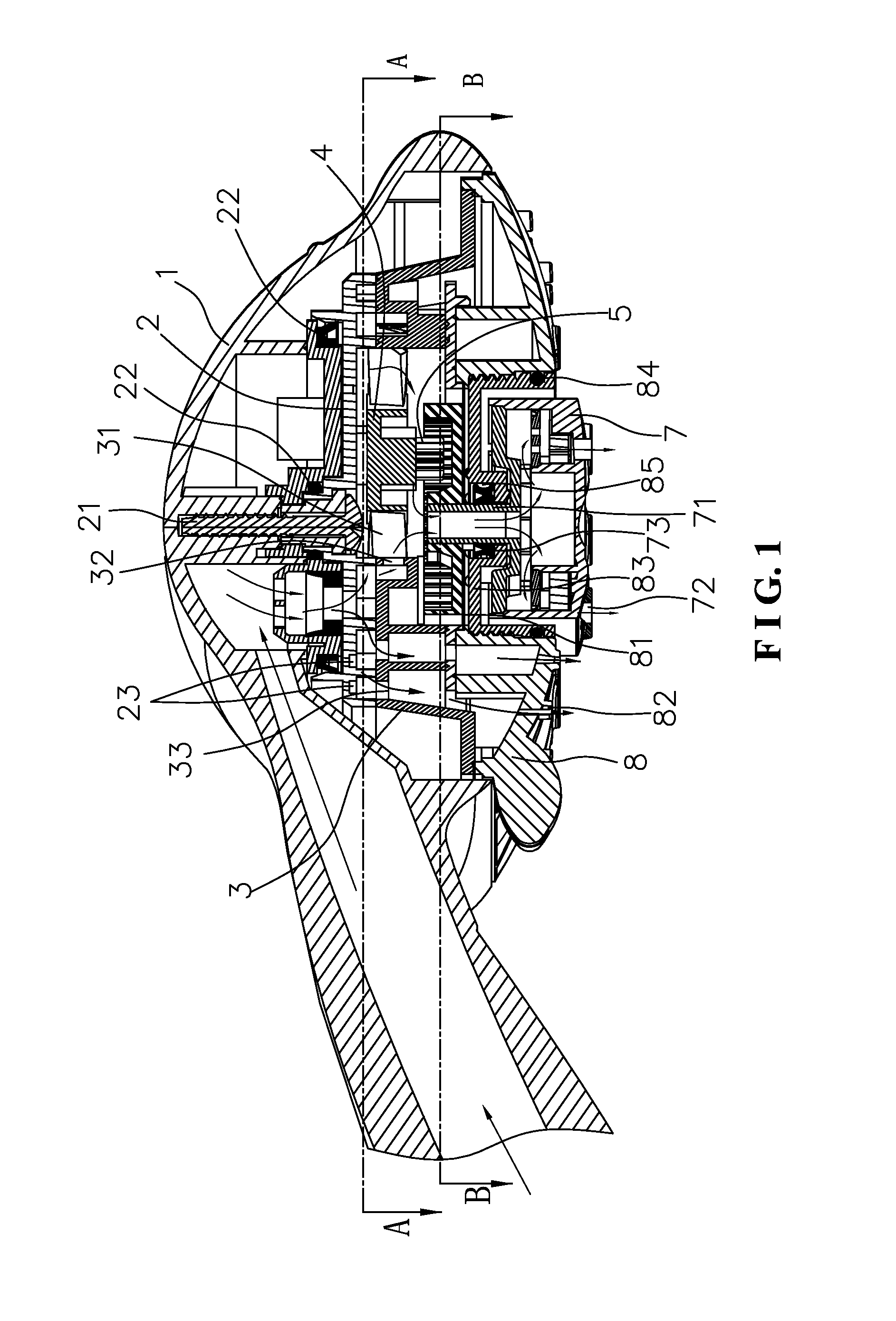
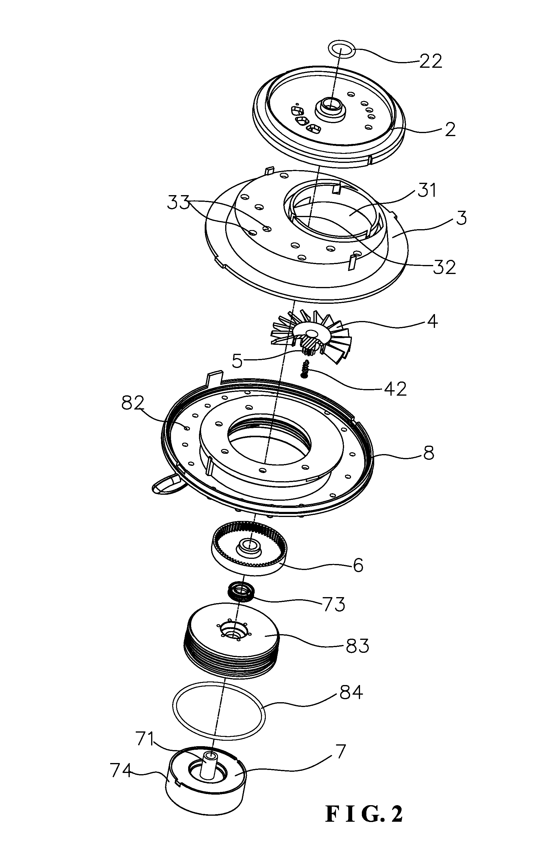
[0027]As shown in FIG. 1 to FIG. 5, the present invention discloses a rotary spray shower head which comprises a main body 1, a water distributing plate 2, a rear faceplate 3, an impeller 4, a pinion 5, a driven gear 6, a water outlet head assembly 7, and a discharge faceplate 8.

[0028]The water distributing plate 2 is assembled under the main body 1 through a screw 21. A seal member 22 is provided between the water distributing plate 2 and the main body 1.

[0029]The impeller 4 is assembled under the water distributing plate 2 through an eccentric shaft 41 cooperating with a screw 42.

[0030]The pinion 5 is concentrically assembled under the impeller 4.

[0031]The rear faceplate 3 is welded under the water distributing plate 2. A power room 31 is formed between the water distributing plate 2 and the rear faceplate 3 for accommodating the impeller 4. Incline...


PUM


Abstract

A rotary spray shower head includes a main body, a water distributing plate, a rear faceplate, an impeller, a pinion, a driven gear, a water outlet head assembly and a discharge faceplate. The present invention is simple in structure. When in use, one portion achieves an ordinary discharge function of the shower head, and another portion achieves a rotary discharge function. The present invention uses the pinion and the driven gear to constitute a planet deceleration. The rotating speed can be controlled, and the rotary spray discharge effect is good.

Description

BACKGROUND OF THE INVENTION[0001]1. Field of the Invention[0002]The present invention relates to a spray shower head, and more particularly to a rotary spray shower head.[0003]2. Description of the Prior Art[0004]On the market, there are many different water discharge structures for a shower head to provide different discharge functions, such as shower water, massage water, mixed water and son on. However, the discharge positions of these functions are fixed. When taking a shower, the water is to wash some certain portions of the user. In particular, in the case of high water pressure, the current momentum is large, and the comfort of taking a shower is poor. The space between the water spouts are not directly washed by the water so the user needs more time and more water to take a shower.[0005]In order to improve the existing water flow state, a shower head to discharge rotary water is developed accordingly, and there are many related patents, such as Chinese Patent No. 20052005760...

Claims


Application Information

Patent Timeline
Patent Type & Authority Applications(United States)
IPC IPC(8): B05B3/04
CPCB05B3/0427B05B1/18B05B1/1654B05B3/0422
Inventor YU, ZHANGJUN
Owner SINYU TECH FUJIAN
Why Eureka
Try Eureka