Micromechanical tunable fabry-perot interferometer and a method for producing the same

a technology of fabryperot and interferometer, which is applied in the direction of optics, instruments, optical elements, etc., can solve the problems of insufficient finesse of such an interferometer for several applications with high finesse, ineffective voltage applied to the electrode at the optical area, and difficult to provide high voltage in small-sized sensor circuits. good performan

Active Publication Date: 2014-04-24
TEKNOLOGIAN TUTKIMUSKESKUS VTT
View PDF1 Cites 25 Cited by
  • Summary
  • Abstract
  • Description
  • Claims
  • Application Information

AI Technical Summary

Benefits of technology

[0043]Since polycrystalline silicon and air both have low attenuation in the infrared range wavelengths it is possible to provide interferometers which have good perfor...

Problems solved by technology

As a result, the finesse of such an interferometer is not sufficiently high for several applications where high finesse is required.
The layer 106 is only connected to control voltage at the area outside the optical area, and the voltage applied to the electrode is thus not effective at the optical area.
However, there are some disadvantages in this approach as well.
It is often difficult to provide high voltages in small-sized sensor circuits, and also energy consumption may increase due to energy losses in a required volt...

Method used


Image

  • Micromechanical tunable fabry-perot interferometer and a method for producing the same
  • Micromechanical tunable fabry-perot interferometer and a method for producing the same
  • Micromechanical tunable fabry-perot interferometer and a method for producing the same

Examples


Embodiment Construction

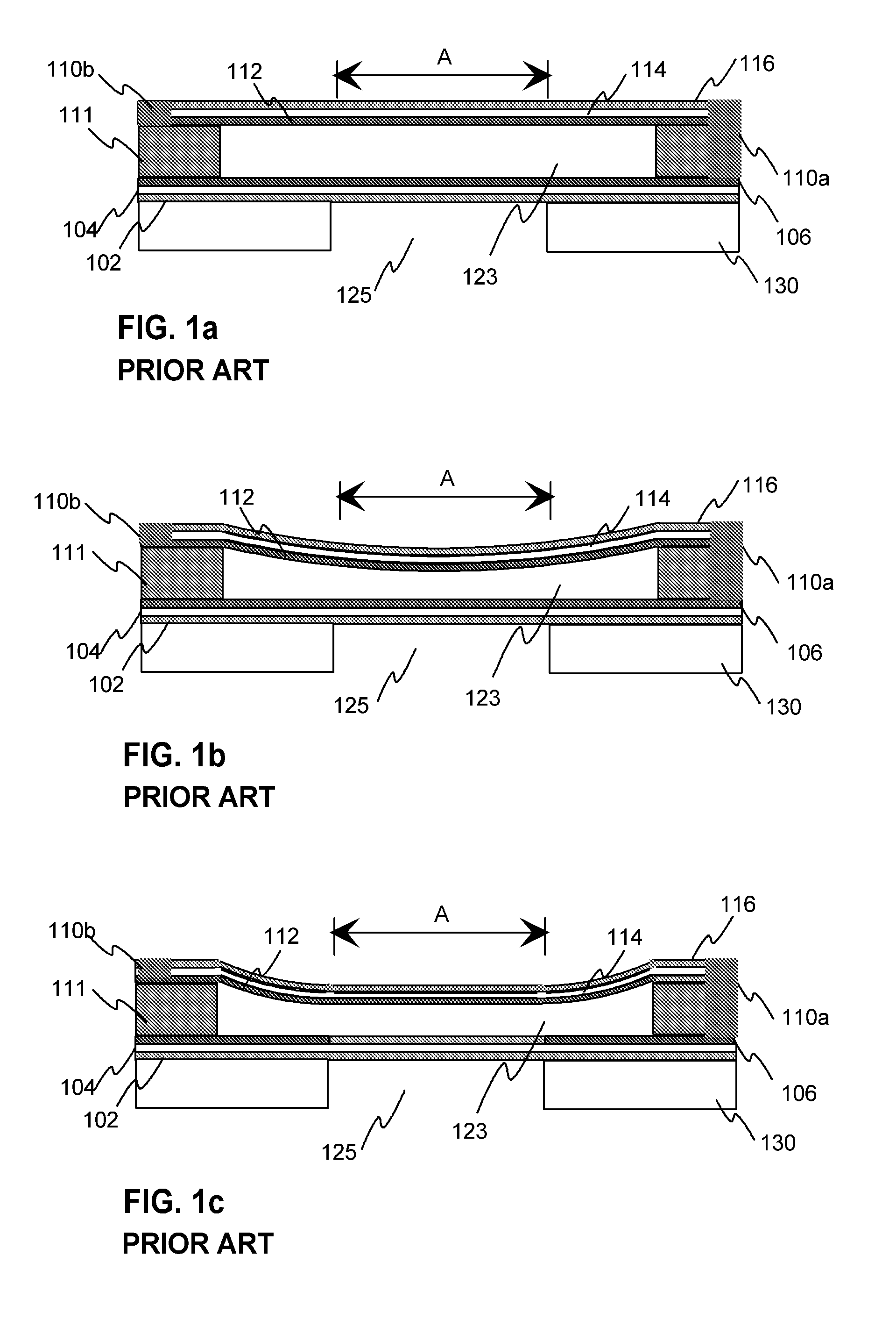
[0059]FIGS. 1a, 1b and 1c were described in the prior art section of the description.

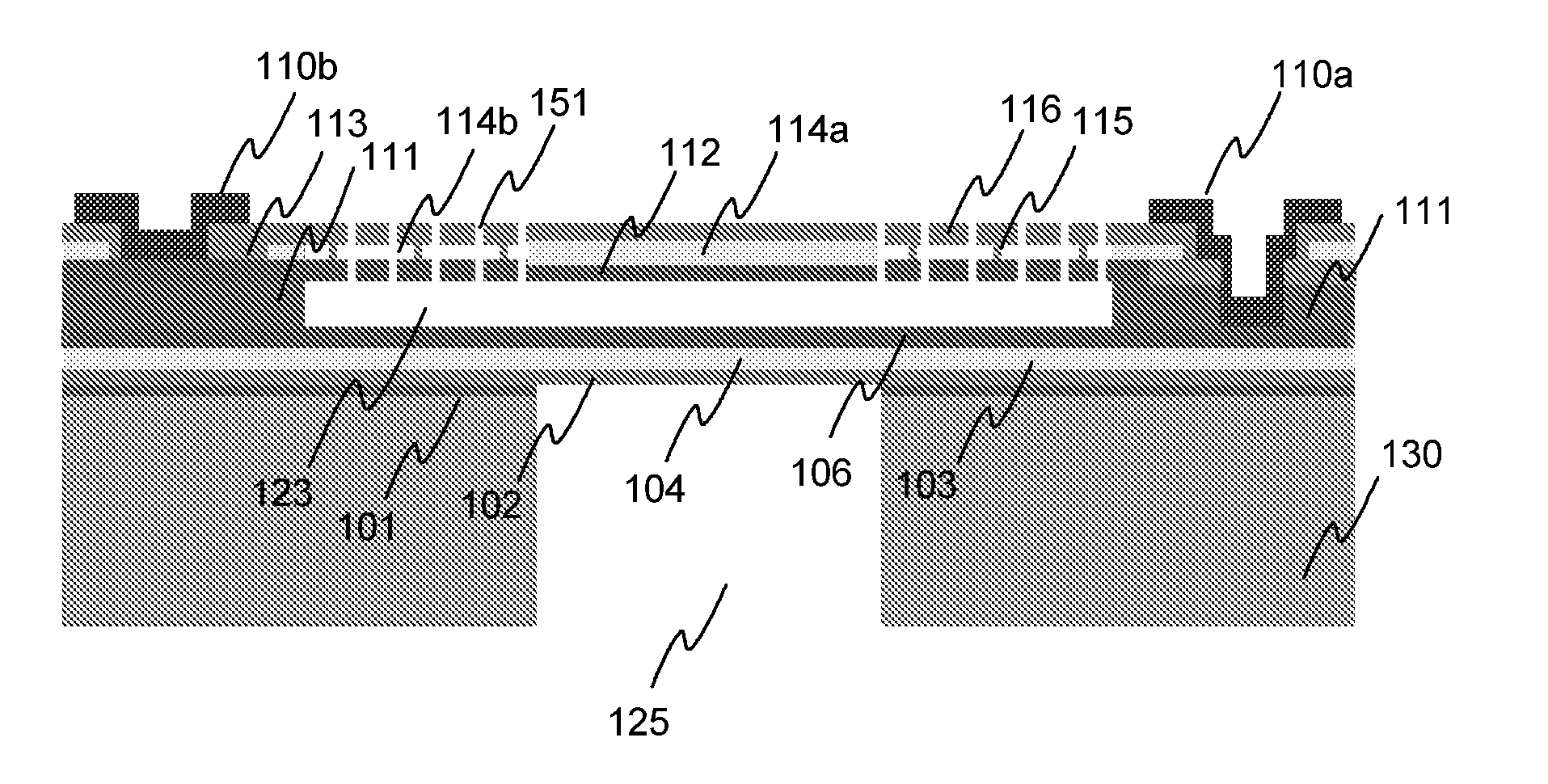
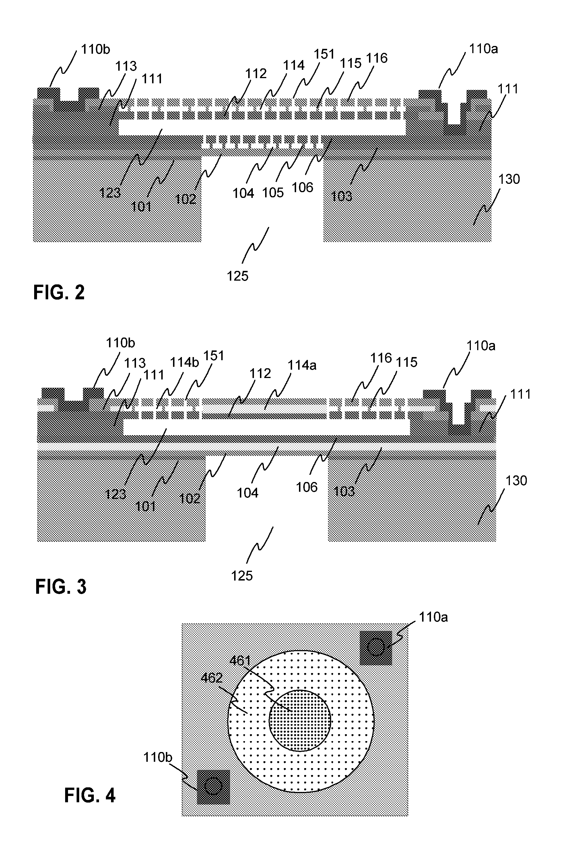
[0060]FIG. 2 illustrates a cross section of an exemplary Fabry-Perot interferometer according to the invention. The interferometer has a substrate 130 of e.g. monocrystalline silicon material, wherein there may be a hole 125 at the optical area of the interferometer, thus providing an optical aperture for the interferometer. If the substrate is heavily doped the substrate layer attenuates the radiation and prevents the transmission of radiation outside the optical aperture. However, an aperture may also be provided with a separate non-transparent layer, without removing the substrate.

[0061]The reflecting layers of the fixed mirror are provided by layers 102, 104, 106, wherein layers 102 and 106 are of polycrystalline silicon, and layer 104 is a gap which includes vacuum, air or other gas which is transparent in the operating wavelength range. The gap has been formed by removing a sacrificial layer o...


PUM

PropertyMeasurementUnit
Densityaaaaaaaaaa
Electric potential / voltageaaaaaaaaaa
Widthaaaaaaaaaa

Abstract

Electrically tunable Fabry-Perot interferometers produced with micro-optical electromechanical (MOEMS) technology. Micromechanical interferometers of the prior art require high control voltage, their production includes complicated production phases, and the forms of the movable mirrors are restricted to circular geometries. In the inventive solution, there is a gap in the movable mirror, whereby mirror layers opposite to the gap are connected with anchoring. The anchoring is such that the stiffness of the mirror is higher at the optical area than at the surrounding area. This way it is possible keep the optical area of the mirror flat even if the control electrodes extend to the optical area. Due to large electrodes, lower control voltages are required.

Description

TECHNICAL FIELD[0001]The invention relates to a Fabry-Perot interferometer and a method for producing a Fabry-Perot interferometer. More specifically, the invention relates to electrically tunable Fabry-Perot interferometers which are produced with micro-opto-electromechanical systems (MOEMS) technology. The technical field of the invention is specified in the preamble of the independent claim.BACKGROUND TECHNOLOGY[0002]Fabry-Perot interferometers are used as optical filters and in spectroscopic sensors, for example. A Fabry-Perot interferometer is based on parallel mirrors, such as quarter wave Bragg reflectors, wherein a Fabry-Perot cavity is formed between the mirrors. The pass band wavelength of a Fabry-Perot interferometer can be controlled by adjusting the distance between the mirrors i.e. the width of the cavity. It is common to use micromechanical technology for producing Fabry-Perot interferometers. Such a solution is described e.g. in patent document F195838.[0003]FIG. 1a ...

Claims


Application Information

Patent Timeline
IPC IPC(8): G01B9/02
CPCG01B9/02049G01J3/26G02B26/001Y10T29/49117
Inventor TUOHINIEMI, MIKKO
Owner TEKNOLOGIAN TUTKIMUSKESKUS VTT
Why Eureka
Try Eureka