PRODUCTION APPARATUS AND PRODUCTION METHOD OF SiC SINGLE CRYSTAL
Inactive Publication Date: 2014-05-01
NIPPON STEEL & SUMITOMO METAL CORP +1
View PDF5 Cites 3 Cited by
Summary
Abstract
Description
Claims
Application Information
AI Technical Summary
This helps you quickly interpret patents by identifying the three key elements:
Problems solved by technology
Method used
Benefits of technology
Benefits of technology
This patent aims to create a production apparatus for SiC single crystals that can effectively cool the seed crystal attached to a seed shaft. The technical effect of this invention is to efficiently produce high-quality SiC single crystals.
Problems solved by technology
However, it is difficult to efficiently cool the seed crystal simply by feeding a gas into the seed shaft.
Method used
Image
Click on the blue label to locate the original text in one second.
Reading with bidirectional positioning of images and text.
Examples
first embodiment
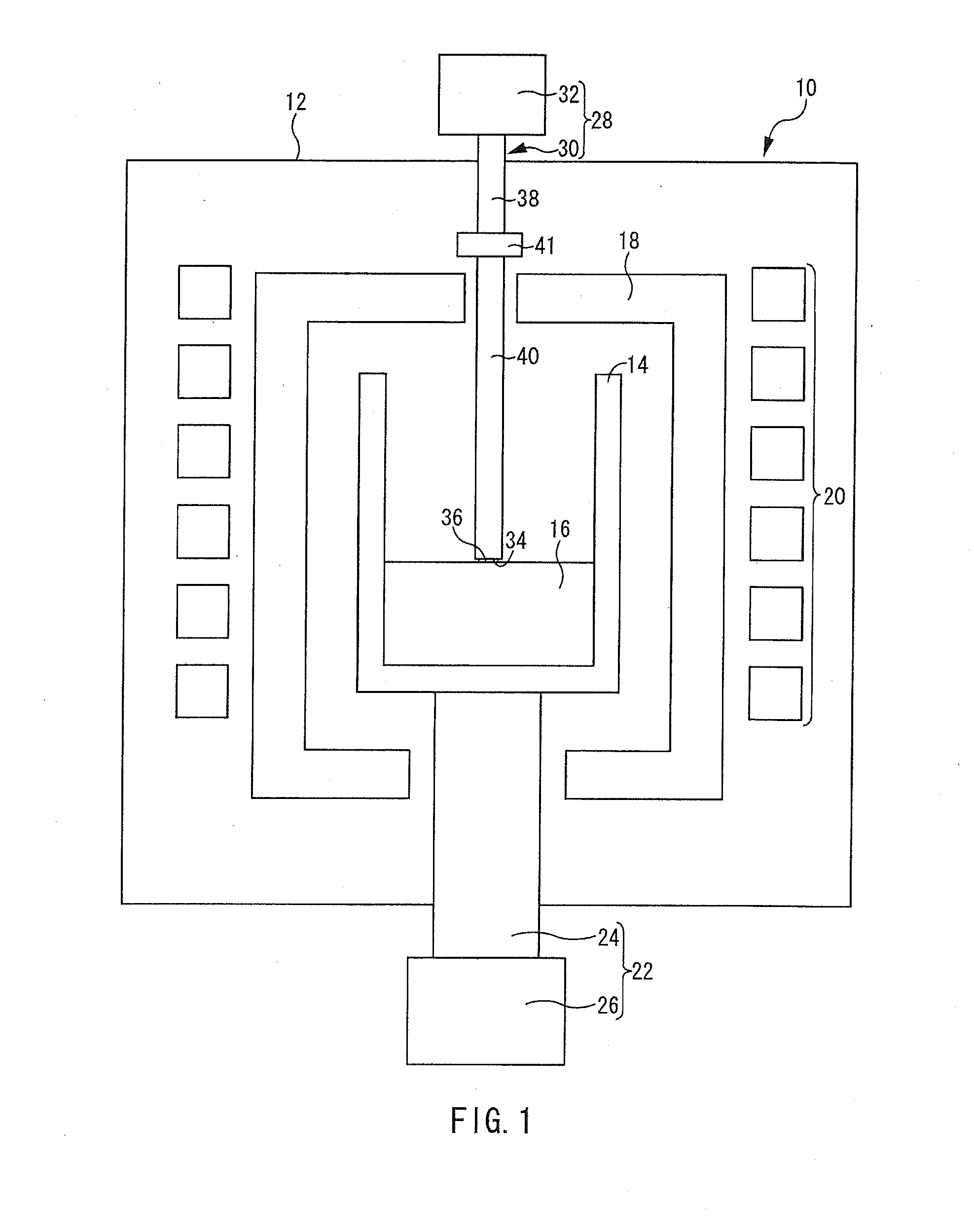
[0024]FIG. 1 is a configuration diagram of a production apparatus 10 of an SiC single crystal according to a first embodiment of the present invention.
[Production Apparatus]
[0025]Referring to FIG. 1, the production apparatus 10 includes a chamber 12. The chamber 12 accommodates a crucible 14. When an SiC single crystal is produced, the chamber 12 is water cooled.
[0026]The crucible 14 accommodates an Si—C solution 16. The Si—C solution 16 is a raw material for the SiC single crystal. The Si—C solution 16 contains silicon (Si) and carbon (C).
[0027]The Si—C solution 16 may be produced, for example, by heating a single substance of Si or a mixture of Si and other metal elements into a melt, and dissolving carbon (C) into the melt. Examples of the other metal elements include titanium (Ti), manganese (Mn), chromium (Cr), cobalt (Co), vanadium (V), iron (Fe), and so on. Among these metal elements, preferable metal elements are Ti, Cr, and Fe. Further preferable metal elements are Ti and C...
application examples 1 and 2
of First Embodiment
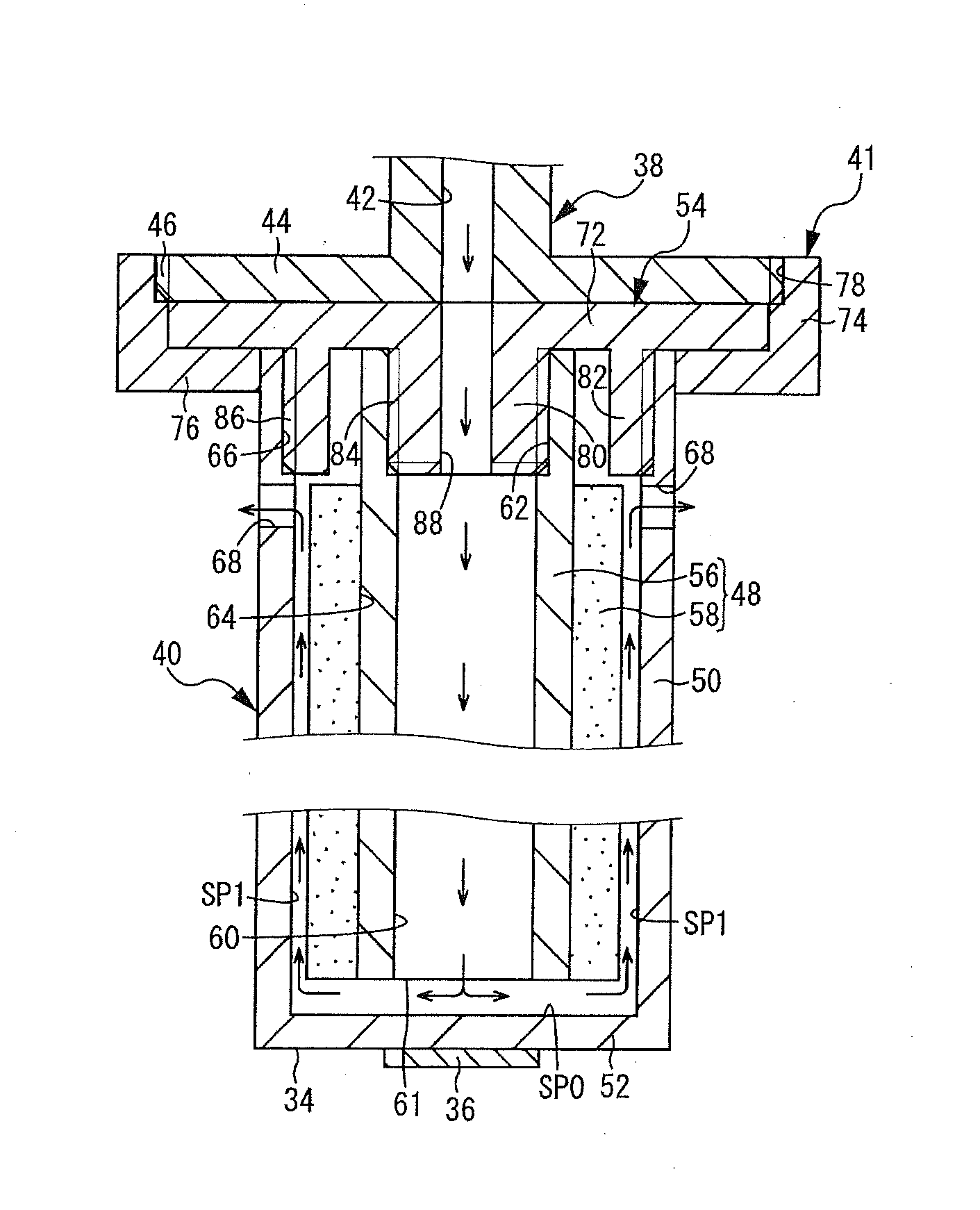
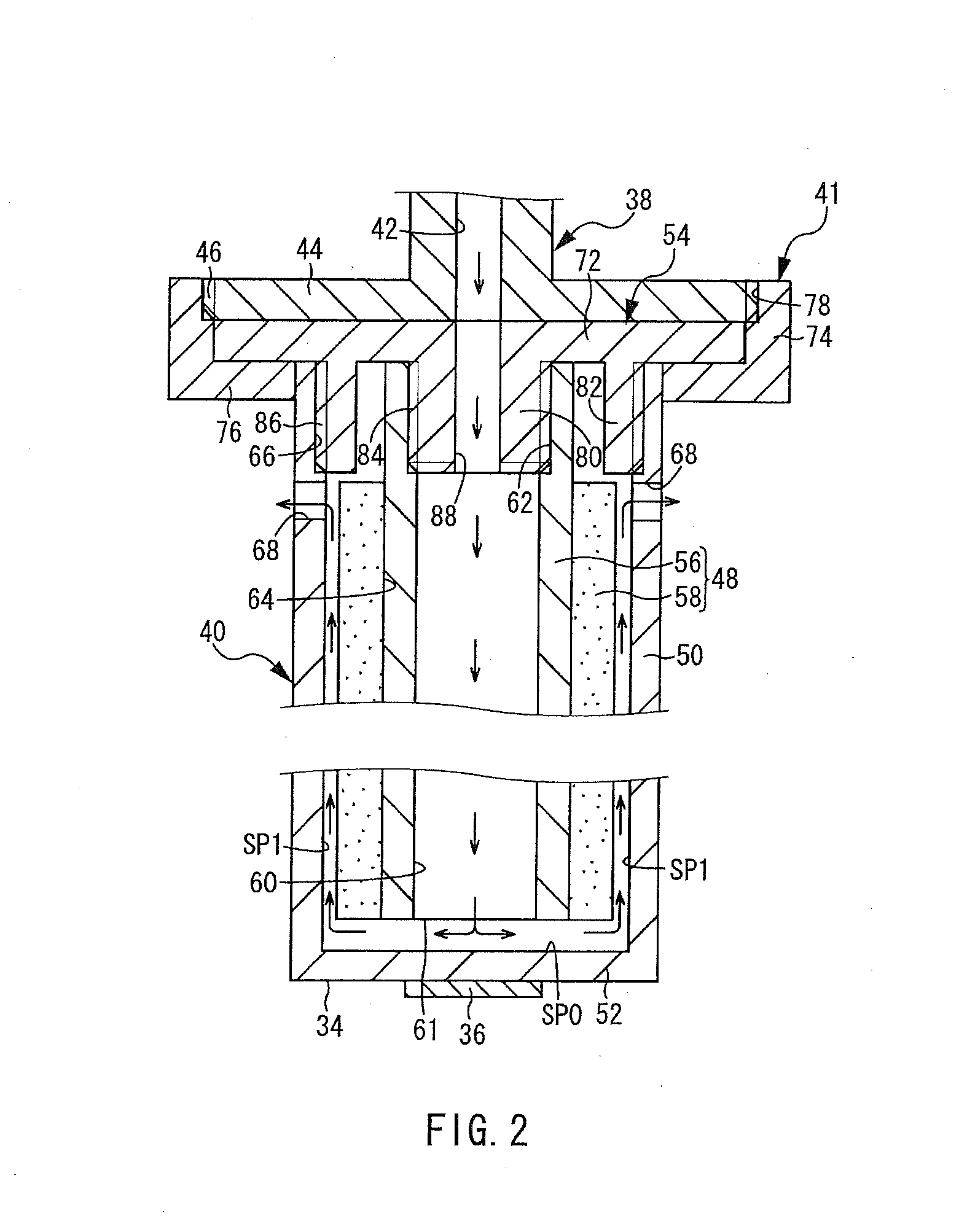
[0084]In the seed shaft 30 shown in FIG. 2, the lower end surface of the inner pipe 48 (the lower end surfaces of the base pipe 56 and the heat insulation pipe 58) is spaced apart from the upper surface of the bottom portion 52. However, the lower end surface of the inner pipe 48 may be in contact with the upper surface of the bottom portion 52. For example, as shown in FIG. 4, the lower end surface of the inner pipe 48 is in contact with the upper surface of the bottom portion 52. One or more communication portions 90 are formed at a lower end portion of the inner pipe 48. In this case, the gas after use which has taken away the heat of the bottom portion 52 flows from the introduction passage 60 into the discharge passage SP1 through the communication portion 90 (application example 1).
[0085]As shown in FIG. 5, the communication portion 90 may be formed above the lower end of the inner pipe 48 (application example 2).
application example 3 of first embodiment
[0086]In the seed shaft 30 shown in FIG. 2, the inner pipe 48 includes the base pipe 56 and the heat insulation pipe 58. However, the configuration of the inner pipe 48 will not be limited to such a configuration. As shown in FIG. 6, the inner pipe 48 may be made up of the heat insulation pipe 58 alone.
PUM
Abstract
An apparatus for producing an SiC single crystal includes a crucible for accommodating an Si—C solution and a seed shaft having a lower end surface where an SiC seed crystal (36) would be attached. The seed shaft includes an inner pipe that extends in a height direction of the crucible and has a first passage. An outer pipe accommodates the inner pipe and constitutes a second passage between itself and the inner pipe and has a bottom portion whose lower end surface covers a lower end opening of the outer pipe. One passage of the first and second passages serves as an introduction passage where coolant gas flows downward, and the other passage serves as a discharge passage where coolant gas flows upward. A region inside the pipe that constitutes the introduction passage is to be overlapped by a region of not less than 60% of the SiC seed crystal.
Description
TECHNICAL FIELD[0001]The present invention relates to a production apparatus of an SiC single crystal, and more particularly to a production apparatus of an SiC single crystal by a solution growth method.BACKGROUND ART[0002]The solution growth method has been known as a method for producing a single crystal of siliconcarbide (SiC). In the solution growth method, an SiC single crystal is grown on an SiC seed crystal which is in contact with an Si—C solution. The Si—C solution is a solution in which carbon (C) is dissolved into a melt of Si or an Si alloy. It is desirable that carbon is dissolved in the solution as much as possible within a composition range in which the solution and the solid phase SiC are at thermodynamic equilibrium. The SiC seed crystal is brought into contact with the Si—C solution (a liquid phase) such that at least a portion of the solution in the vicinity of the seed crystal is supercooled. This creates a supersaturated condition of SiC in the portion of the ...
Claims
Application Information
Patent Timeline
Application Date:The date an application was filed.
Publication Date:The date a patent or application was officially published.
First Publication Date:The earliest publication date of a patent with the same application number.
Issue Date:Publication date of the patent grant document.
PCT Entry Date:The Entry date of PCT National Phase.
Estimated Expiry Date:The statutory expiry date of a patent right according to the Patent Law, and it is the longest term of protection that the patent right can achieve without the termination of the patent right due to other reasons(Term extension factor has been taken into account ).
Invalid Date:Actual expiry date is based on effective date or publication date of legal transaction data of invalid patent.

