Adsorption Desulfurization Process for Hydrocarbons and a Reaction Apparatus Therefor

a technology of desulfurization process and hydrocarbons, which is applied in the direction of vortex flow apparatus, lighting and heating apparatus, furnaces, etc., can solve the problems of affecting the desulfurization effect and normal operation, the formation of catalyst fine powder, and the fine powder of catalysts, so as to achieve effective removal of fine catalyst powder, stable flow, and low flow rate

Active Publication Date: 2014-05-01
CHINA PETROCHEMICAL CORP +1
View PDF7 Cites 171 Cited by
  • Summary
  • Abstract
  • Description
  • Claims
  • Application Information

AI Technical Summary

Benefits of technology

[0030]The adsorption desulfurization reaction apparatus of the present invention can not only accomplish the adsorption desulfurization of a sulfur-containing hydrocarbon feedstock and the regeneration and reduction of a spent catalyst, but also duly remove the fine catalyst powder produced in the adsorption desulfurization from the adsorption desulfurization reactor.
[0031]The airflow particle sorter of the adsorption desulfurization reaction apparatus of the present invention can effectively sort out catalyst particles with larger particle size from the hydrocarbon-catalyst mixture coming from the settling zone, and send them back to the reaction zone. The fine catalyst powder is sent out of the fluidized bed reactor together with hydrocarbon products. The reason why the airflow particle sorter can achieve the above effect lies in that: the inner space of the sorter main body comprises the straight tube zone and the cone zone, the directing-intake port and the directing-outtake port are located in the straight tube zone and separated by a certain distance with each other, and a sealed bottom end is located under the directing-outtake port. In the adsorption desulfurization condition, when the airflow particle sorter separates and sorts catalyst particles in the hydrocarbon-catalyst mixture entering the inner space of the sorter main body, the inner space can provide a stable centrifugal force field for the separation and sorting so as to accomplish the sorting of catalyst particles in the hydrocarbon-catalyst mixture and effectively remove the fine catalyst powder from the fluidized bed reactor.
[0032]In the separation space of the airflow particle sorter in the adsorption desulfurization reaction apparatus of the present invention, the gas stream has a low flow rate and a stable flow, and therefore there is a low probability for secondarily crushing the catalyst during the separation and sorting.

Problems solved by technology

Because the sulfur element has a larger atom radius than the oxygen element, therefore in the reaction-regeneration cycle, it is inevitable that the crystal lattice of the catalyst changes and even the crushing of catalyst particles may occur, resulting in the formation of catalyst fine powder.
After the long term collision and abrasion among catalyst particles, the crushing will occur, which also results in the formation of catalyst fine powder.
The solid particles having a size of e.g. greater than 2 μm is prone to remain in the reaction system, resulting in that a large amount of catalyst fine powder with a smaller particle size cannot be duly removed from the reactor, and therefore the desulfurization effect and the normal operation are impacted.
Where a conventional cyclone separator is provided in the adsorption desulfurization reactor to separate the catalyst, due to the high gas flow rate in the cyclone separator, upon separating the hydrocarbon product from catalyst particles, there will be intense collision among particles and between the particles and the cyclone separator's walls, which is prone to cause the crushing of the catalyst.
This results in that the catalyst fine powder in the fluidized bed reactor cannot be effectively separated and sorted out.
Furthermore, due to the substantive crushing of catalyst, the quantity of the catalyst fine powder in the fluidized bed reactor increases, and therefore the catalyst consumes faster.
Based on this, it still needs a sorter that can effectively separate solid particles with larger size from a gas stream entraining solid particles, and will not exacerbate the crushing of catalyst particles.

Method used


Image

  • Adsorption Desulfurization Process for Hydrocarbons and a Reaction Apparatus Therefor
  • Adsorption Desulfurization Process for Hydrocarbons and a Reaction Apparatus Therefor
  • Adsorption Desulfurization Process for Hydrocarbons and a Reaction Apparatus Therefor

Examples


example 1

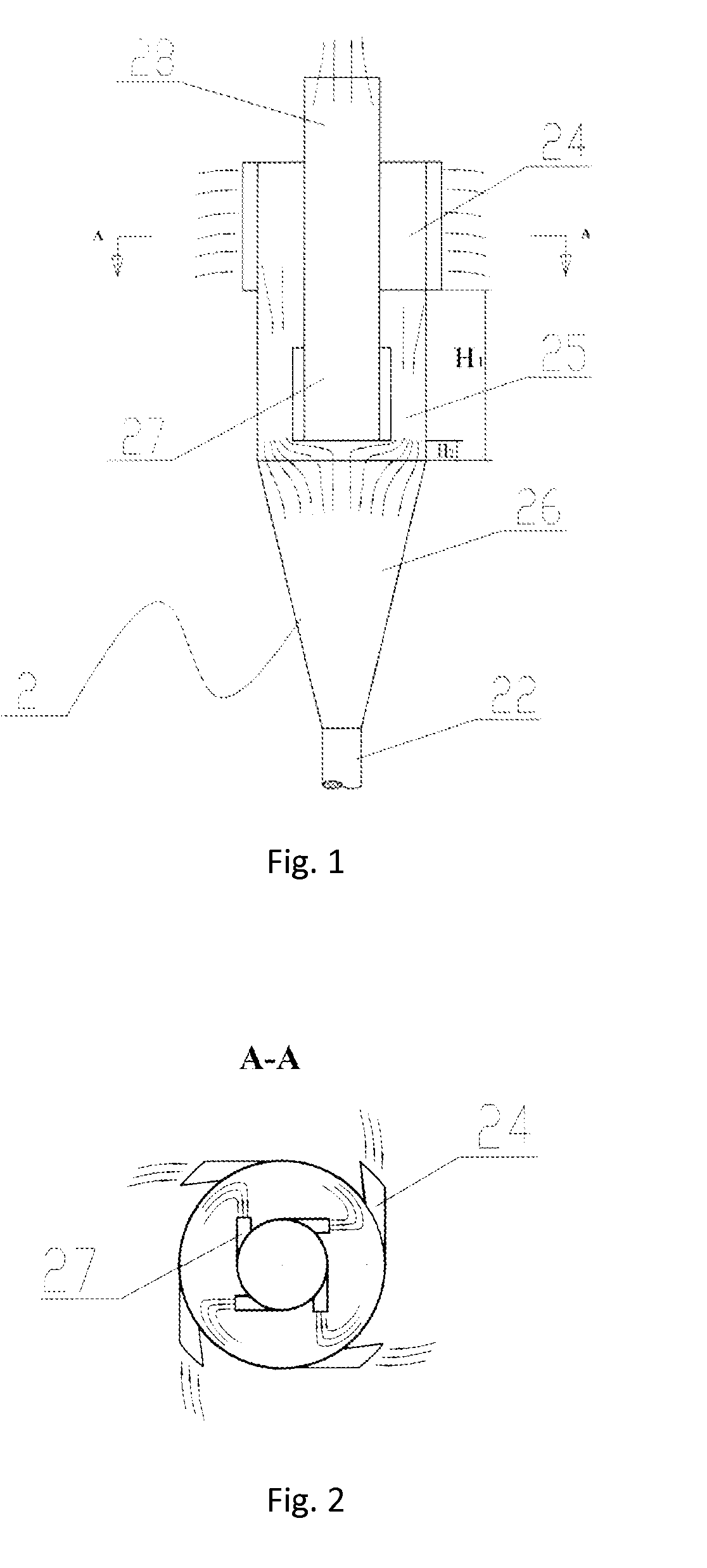
[0160]In this example, the straight tube zone of the airflow particle sorter was installed with 4 directing-intake ports in its tangential direction (the directing-intake ports were distributed in the circumferential direction of the straight tube zone (as shown in FIG. 2), and each of the directing-intake ports had the same cross-section area perpendicular to the airflow direction); the outtake tube of the airflow particle sorter was installed with 4 directing-outtake ports in its tangential direction (the directing-outtake ports were distributed in the circumferential direction of the outtake tube (as shown in FIG. 2), and each of the directing-outtake ports had the same cross-section area perpendicular to the airflow direction); the difference between the horizontal cross-section area of the straight tube zone and the horizontal cross-section area of the outtake tube was A0, the total cross-section area perpendicular to the airflow direction of the directing-intake port was A1, t...

example 2

[0167]The adsorption desulfurization was conducted in the same manner as Example 1, except that A1 / A0 was 0.24:1, A2 / A0 was 0.15:1, the linear velocity of the hydrocarbon-catalyst mixture at the directing-intake port of the airflow particle sorter was 2.5 m / s, and the linear velocity at the directing-outtake port of the airflow particle sorter was 4 m / s.

[0168]The reaction was continuously conducted for 500 hours. During the reaction, the composition of the obtained hydrocarbon product, the average particle size of the catalyst in the catalyst fine powder storage tank, and the average particle size of the catalyst in the catalyst dense bed of the fluidized bed reactor were monitored. The results were listed in Table 4. After 500 hours of reaction, in the catalyst in the dense bed of the fluidized bed reactor, the content of the catalyst having a particle size of less than 30 μm was 9.5 wt %. A total of 14.2 kg catalyst was charged into the fluidized bed reactor before the reaction, a...

example 3

[0175]The adsorption desulfurization was conducted in the same manner as Example 1, except that the straight tube zone of the airflow particle sorter was installed with 6 directing-intake ports in its tangential direction (the directing-intake ports were distributed in the circumferential direction of the straight tube zone (as shown in FIG. 2), and each of the directing-intake ports had the same cross-section area perpendicular to the airflow direction); the outtake tube of the airflow particle sorter was installed with 6 directing-outtake ports in its tangential direction (the directing-outtake ports were distributed in the circumferential direction of the outtake tube (as shown in FIG. 2), and each of the directing-outtake ports had the same cross-section area perpendicular to the airflow direction);

[0176]the difference between the horizontal cross-section area of the straight tube zone and the horizontal cross-section area of the outtake tube was A0, the total cross-section area...


PUM

PropertyMeasurementUnit
temperatureaaaaaaaaaa
pressureaaaaaaaaaa

Abstract

The present invention relates to an airflow particle sorter, comprising: a top-sealed sorter main body, a discharge port, an outtake tube and at least one directing-intake port; the inner space of the sorter main body, from the above to the bottom, includes, a straight tube zone and a cone zone, the conical bottom of the cone zone is connected to the straight tube zone; the discharge port is located at the bottom of the cone zone; the directing-intake port is installed in the upper part of the straight tube zone in a tangential direction of the straight tube zone, and is communicated with the inner space of the sorter main body; the outtake tube is hermetically inserted into the top of the sorter main body, and extends downwardly to the lower part of the straight tube zone, and the outtake tube has a sealed bottom end; the lower part of the outtake tube is installed with at least one directing-outtake port, which communicates the outtake tube with the inner space of the sorter main body, the directing-outtake port is installed in a tangential direction of the outtake tube. The present invention further relates to a fluidized bed reactor and an adsorption desulfurization reaction apparatus as well as an adsorption desulfurization process.

Description

TECHNICAL FIELD[0001]The present invention relates to an airflow particle sorter, an adsorption desulfurization reaction apparatus comprising the airflow particle sorter, and an adsorption desulfurization process using the adsorption desulfurization reaction apparatus.BACKGROUND ART[0002]In the adsorption desulfurization for hydrocarbons, the sulfur element in the hydrocarbon feedstock is fixed, e.g. by converting the sulfur element in sulfur containing hydrocarbons to zinc sulfide. By passing oxygen to the regenerator and combusting therein, zinc sulfide in the catalyst particles and oxygen are reacted to form zinc oxide and sulfur dioxide, and therefore the adsorption activity of the catalyst is recovered.[0003]Because the sulfur element has a larger atom radius than the oxygen element, therefore in the reaction-regeneration cycle, it is inevitable that the crystal lattice of the catalyst changes and even the crushing of catalyst particles may occur, resulting in the formation of ...

Claims


Application Information

Patent Timeline
Patent Type & Authority Applications(United States)
IPC IPC(8): C07C7/12
CPCC07C7/12C10G25/09C10G45/02B01J8/0055B01J8/24B01J8/26B04C5/08B04C5/103C10G25/12C10G45/20
Inventor LONG, JUNTIAN, ZHIHONGHOU, SHUANDIZHU, BINGTIANWU, XUEFENGZHANG, JIUSHUNMAO, ANGUOZHANG, ZHEMINLV, LUFENGHE, JINLONGLI, XUEFENGLIU, YALIN
Owner CHINA PETROCHEMICAL CORP
Why Eureka
Try Eureka