Systems and methods for implementing magnetoelectric junctions having improved read-write characteristics

a technology of magnetoelectric junctions and read-write characteristics, applied in the field of magnetoelectric junction implementation, can solve the problems of inefficiency and widespread adoption, and achieve the effect of reducing the coercivity of the ferromagnetic free layer

Active Publication Date: 2014-05-08
RGT UNIV OF CALIFORNIA
View PDF8 Cites 76 Cited by
  • Summary
  • Abstract
  • Description
  • Claims
  • Application Information

AI Technical Summary

Benefits of technology

[0009]In still another embodiment, the coercivity of the ferromagnetic free layer is reduced when a potential difference is applied across the magnetoelectric junction.
[0010]In still yet another embodiment, the application of a first threshold potential difference across the ferromagnetic fixed layer and the ferromagnetic free layer reduces the coercivity of the ferromagnetic free layer to an extent where the strength of the magnetic field imposed by the ferromagnetic fixed layer is sufficient to cause the ferromagnetic free layer to adopt a magnetic polarity that is determined by that of the ferromagnetic fixed layer.

Problems solved by technology

MRAM technologies initially exhibited a number of deficiencies.
In particular, they tended to be inefficient since they required a relatively large current to manipulate the magnetic polarization of the bit's free layer.
Nonetheless, in spite of these advances to MRAM technology and in spite of the many potential advantages that MRAM technology offers, it has yet to achieve widespread adoption.

Method used


Image

  • Systems and methods for implementing magnetoelectric junctions having improved read-write characteristics
  • Systems and methods for implementing magnetoelectric junctions having improved read-write characteristics
  • Systems and methods for implementing magnetoelectric junctions having improved read-write characteristics

Examples


Embodiment Construction

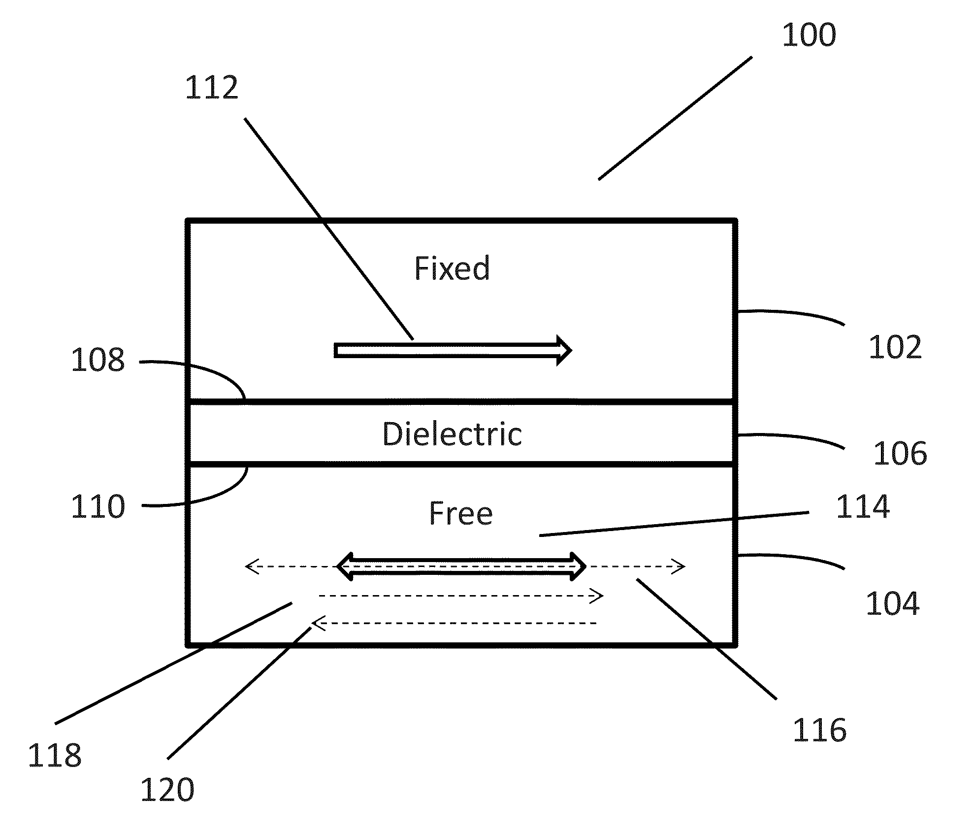
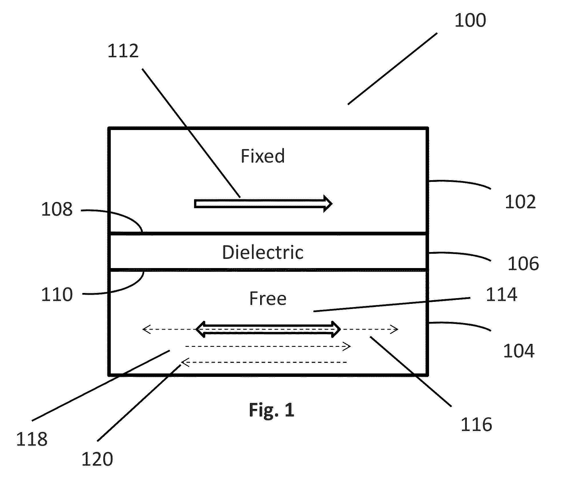
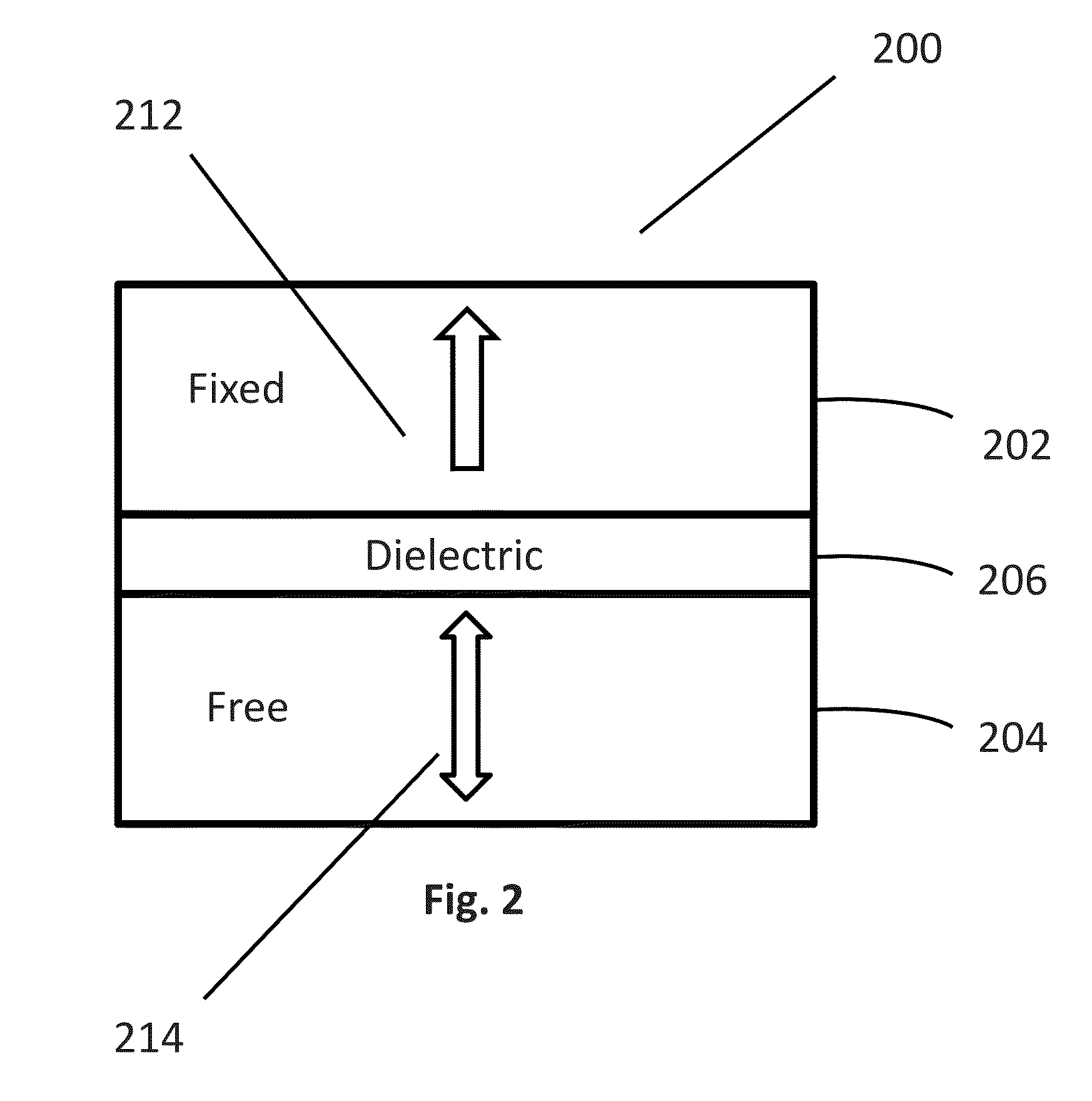
[0044]Turning now to the drawings, systems and methods for implementing magnetoelectric junctions that have improved read and write characteristics are illustrated. In many embodiments, the read and write characteristics of a magnetoelectric junction are improved by implementing a layer of material that enhances the tunnel magnetoresistance (TMR) effects that a magnetoelectric junction generally relies on during the ‘reading’ aspect of its operation, and a separate layer of material that enhances the voltage controlled-magnetic anisotropy (VCMA) effects that a magnetoelectric junction generally relies on during the ‘writing’ aspect of its operation. In a number of embodiments, a first dielectric layer is used to enhance the TMR effects, and a second dielectric layer of material is used to enhance the VCMA effects. In some embodiments, a layer of material with a high spin-orbit coupling is used to enhance the VCMA effects.

[0045]Previous efforts at implementing electromagnetic compone...


PUM


Abstract

Embodiments of the invention implement MEJs having improved read-write characteristics. In one embodiment, an MEJ includes: ferromagnetic fixed and free layers, a dielectric layer interposed between the ferromagnetic layers, and an additional dielectric layer proximate the free layer, where the fixed layer is magnetically polarized in a first direction, where the free layer has a first easy axis that is aligned with the first direction, and where the MEJ is configured such that when subject to a potential difference, the magnetic anisotropy of the free layer is altered such that the relative strength of the magnetic anisotropy along a second easy axis that is orthogonal to the first easy axis, compared to the strength of the magnetic anisotropy along the first easy axis, is magnified during the application of the potential difference, where the extent of the magnification is enhanced by the presence of the additional layer.

Description

CROSS-REFERENCE TO RELATED APPLICATIONS[0001]The current application claims priority to U.S. Provisional Application No. 61 / 723,289, filed Nov. 6, 2012, the disclosure of which is incorporated herein by reference.FIELD OF THE INVENTION[0002]The present invention generally relates to the implementation of magnetoelectric junctions.BACKGROUND OF THE INVENTION[0003]Devices that rely on the interplay between electricity and magnetism underlie much of modern electronics. Relatively recently, researchers have begun to develop and implement such devices that take advantage of quantum mechanical magnetoresistance effects, such as giant magnetoresistance (GMR) and tunnel magnetoresistance (TMR). GMR and TMR principles regard how the resistance of a thin film structure that includes alternating layers of ferromagnetic and non-magnetic layers depends upon whether the ferromagnetic layers are in a parallel or antiparallel alignment. For example, magnetoresistive random-access memory (MRAM) is a...

Claims


Application Information

Patent Timeline
Patent Type & Authority Applications(United States)
IPC IPC(8): H01L43/02G11C11/16H01L43/10
CPCH01L43/02H01L43/10G11C11/161G11C11/18H10B61/10H10N50/10H10N50/85
Inventor KHALILI AMIRI, PEDRAMWANG, KANG L.
Owner RGT UNIV OF CALIFORNIA
Why Eureka
Try Eureka