Large area ground monitoring

a large-area ground and object technology, applied in the field of large-area ground monitoring, can solve the problems of deeper, dangerous, harmful objects, value, critical, etc., and achieve the effect of improving false positive performan

Inactive Publication Date: 2014-05-08
STOLAR
View PDF15 Cites 18 Cited by
  • Summary
  • Abstract
  • Description
  • Claims
  • Application Information

AI Technical Summary

Benefits of technology

[0026]Other embodiments of the present invention build in so-called “rejection zones” which are tuned to the surface depths subject to such inconsequential dielectric variations. Valuable, critical, dangerous and harmful objects will be deeper, in the layers

Problems solved by technology

Valuable, critical, dangerous and harmful objects will be deeper, in the layers usually obscu

Method used


Image

  • Large area ground monitoring
  • Large area ground monitoring
  • Large area ground monitoring

Examples


Embodiment Construction

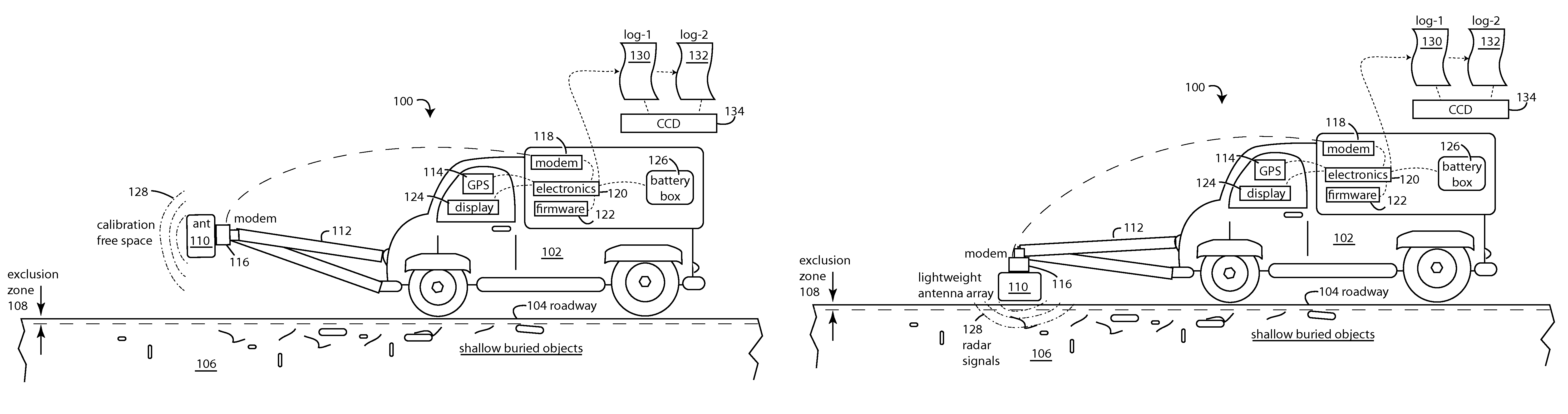
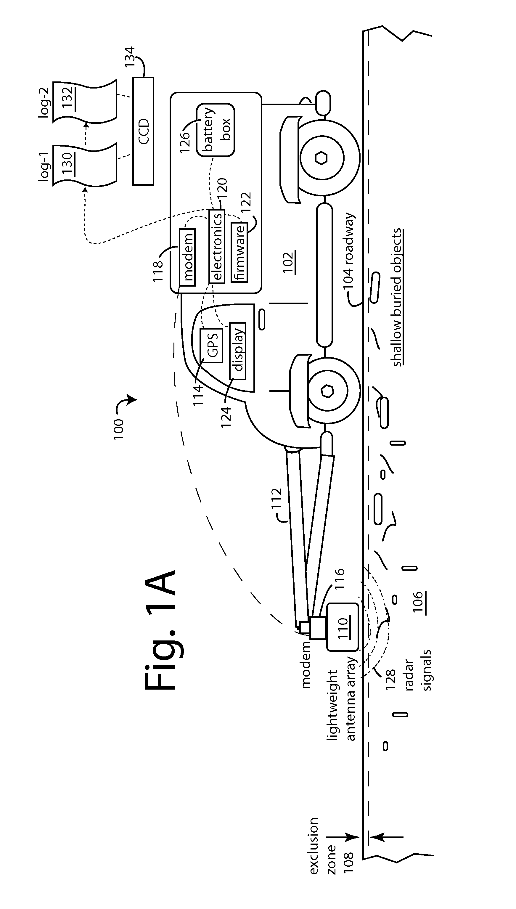
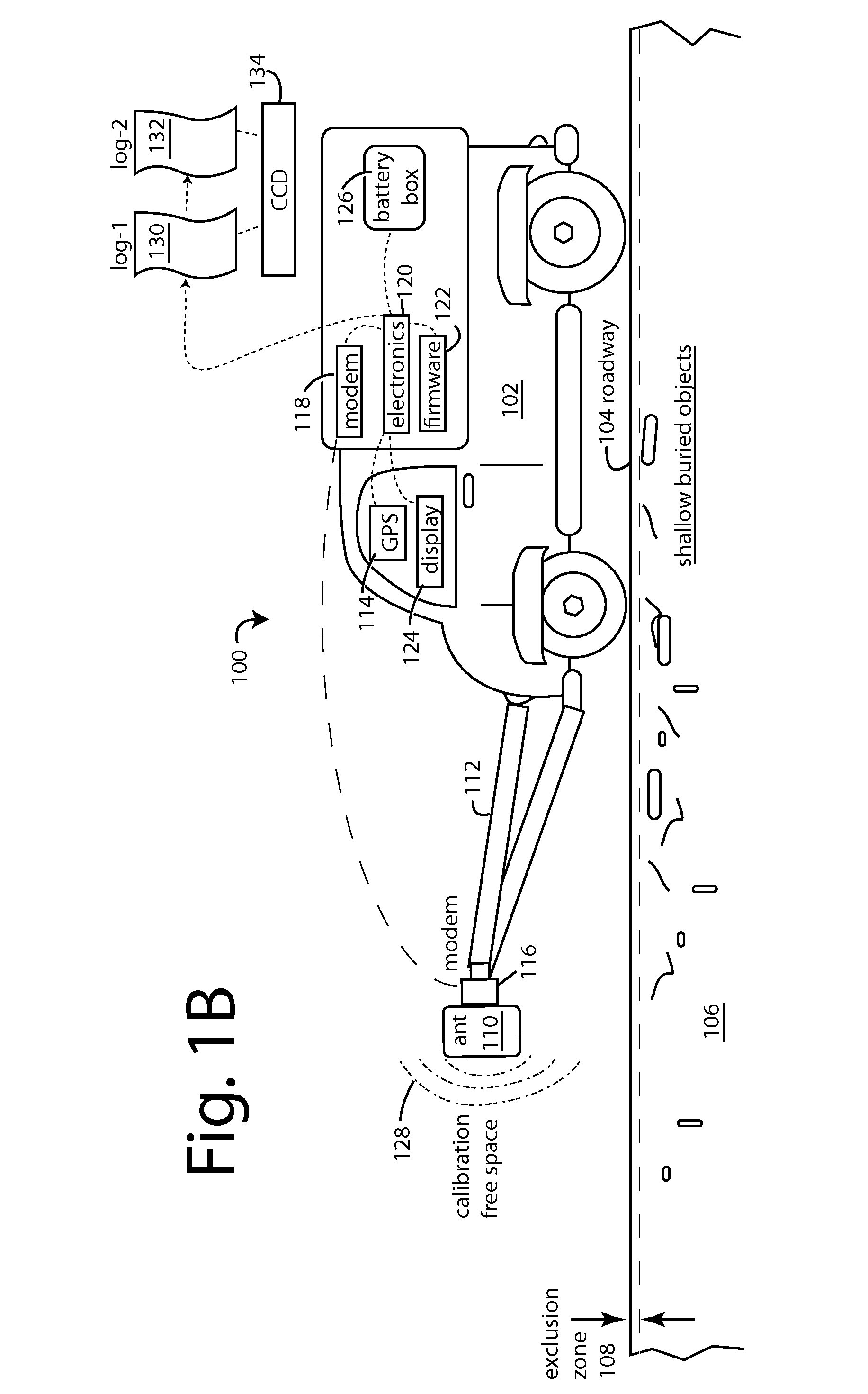
[0041]FIGS. 1A and 1B represent a municipal infrastructure maintenance system 100 that uses a typical ground vehicle to move a lateral antenna array over large areas or long distances.

[0042]FIG. 1B illustrates how such antenna array can be pivoted up to point forward into free space for antenna calibration. A truck 102 is normally driven over a common roadway 104.

[0043]A clutter 106 of subsurface objects will always exist shallowly in and under roadway 104. These represent pieces of municipal infrastructure, natural artifacts, long ago buried debris, and recently buried things. Above-the-surface and very shallow objects that are usually of no interest are excluded from investigation when an exclusion zone 108 is electronically implemented with radar techniques described herein.

[0044]During operation, a lightweight, multi-element, multi-compartment, lateral linear antenna array 110 is lowered down into position on a hydraulic or winched boom 112 about one foot over roadway 104. A glo...


PUM


Abstract

A municipal infrastructure maintenance system uses a ground vehicle to move an antenna array in back-and-forth sweeps over large areas or distances. The antenna array comprises dozens of compartmentalized radio dipole antennas arranged laterally, shoulder-to-shoulder across the width of each sweep. An antenna switch matrix is connected between the antenna array and a ground-penetrating-radar (GPR) set and provides electronic aperture switching and selection, and the ability to laterally register one sweep to the next. The antenna array is extended out in front of the ground vehicle on a pivotable boom, and the cantilevered weight is a primary concern. The antenna array is constructed with aluminum-on-aluminum honeycomb panels slotted and folded around dozens of resistive-card compartment separators. Printed circuit boards with matching baluns are also slotted to receive tabs on the resistive cards, and their dipole elements are resistive loaded to quench crosstalk and near field effects.

Description

RELATED APPLICATIONS[0001]This Application claims benefit of U.S. Provisional Patent Application 61 / 750,318 filed Jan. 8, 2013, and titled PREDISTORTED DOUBLE SIDEBAND GROUND PENETRATING GRADIOMETRIC RADAR WITH SUPPRESSION OF CLUTTERING REFLECTIONS, by Larry G. Stolarczyk; and it also claims benefit of and is a continuation-in-part of U.S. patent application Ser. No. 13 / 862,379, filed Apr. 13, 2013, and titled, ELECTROMAGNETIC[0002]DETECTION AND IMAGING TRANSCEIVER (EDIT) AND ROADWAY TRAFFIC DETECTION SYSTEM, by Larry G. Stolarczyk; and also a continuation-in-part of U.S. patent application Ser. No. 13 / 301,762, filed Nov. 21, 2011, and titled, UNSYNCHRONIZED RADIO IMAGING, by Igor Bausov, Gerald Stolarczyk, and Larry G. Stolarczyk.BACKGROUND[0003]1. Field of the Invention[0004]The present invention relates to the electronic sensing of shallow buried objects in the ground surface over large areas, and more particularly to maintenance systems for monitoring changing conditions and det...

Claims


Application Information

Patent Timeline
IPC IPC(8): G01S7/41G01S13/88
CPCG01S13/885G01S7/414G01V3/12G01V3/17G01S7/027H01Q1/3216H01Q1/521H01Q21/062
Inventor STOLARCZYK, GERALD L.VALENTINE, CHANCE DAINHUTCHINS, JEFFREY D.BRIGGS, MATTHEW L.MAIN, RICHARD BREWSTERUHL, BRECKEN H.
Owner STOLAR
Why Eureka
Try Eureka