
Radar for rejecting and looking past surface reflections

a technology of surface reflection and radar, applied in the field of electromagnetic sensing, can solve the problems of deeper value, critical, dangerous and harmful objects, etc., and achieve the effect of improving false positive performan

Inactive Publication Date: 2014-05-08
STOLAR
View PDF3 Cites 53 Cited by
  • Summary
  • Abstract
  • Description
  • Claims
  • Application Information

AI Technical Summary

Benefits of technology

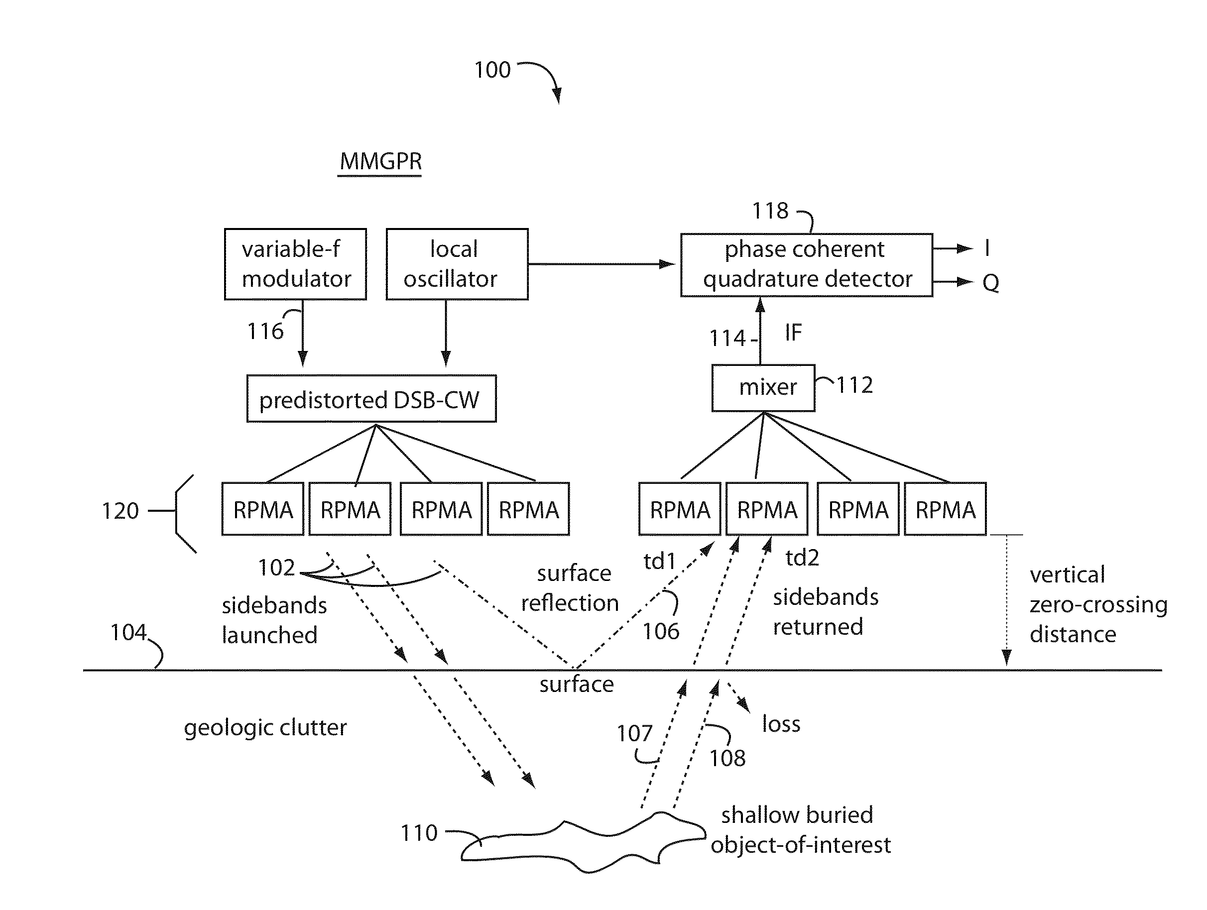
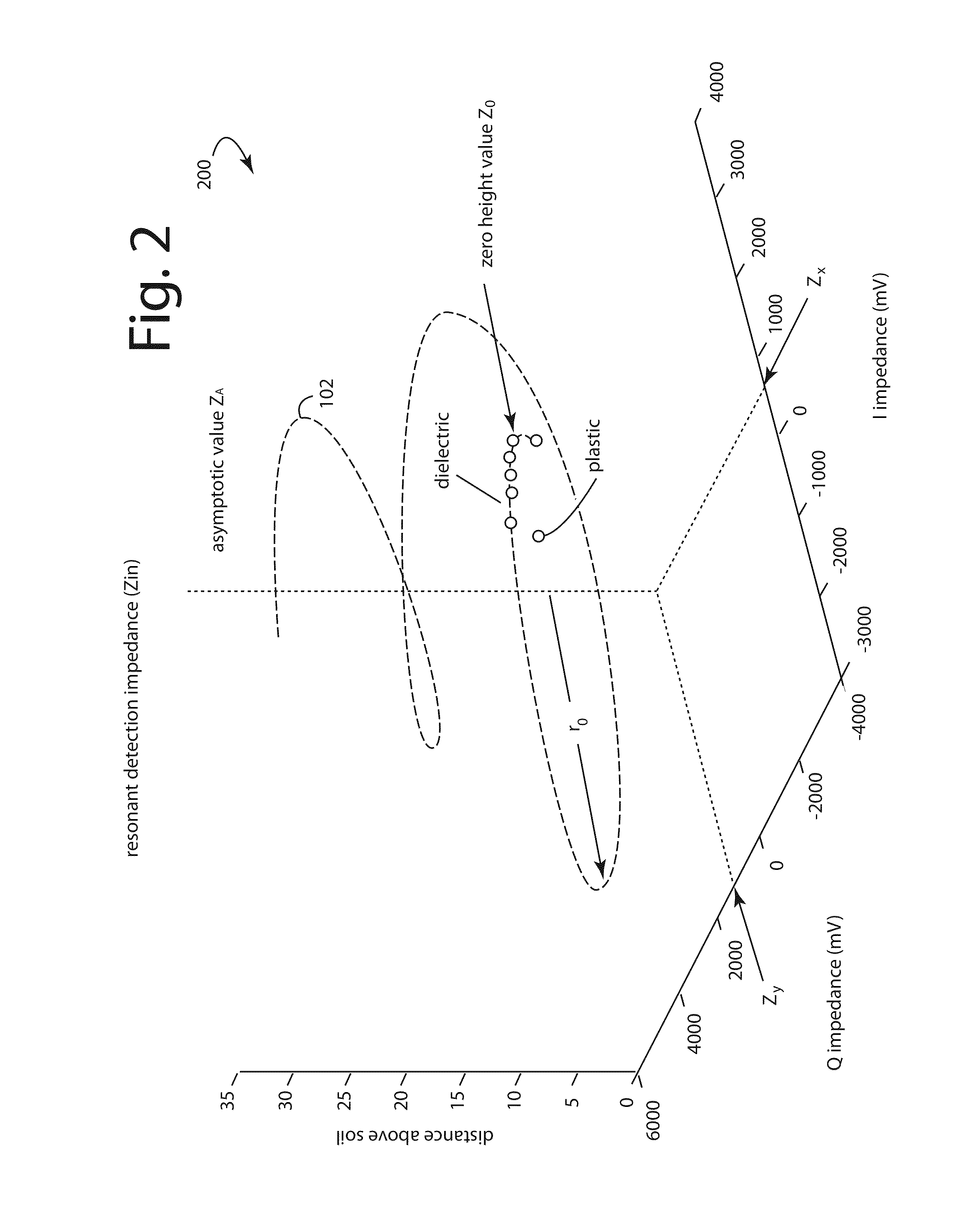
This patent presents various techniques to improve the performance of radar systems by using "rejection zones" that can be adjusted to the surface depths where inconsequential dielectric variations occur. These techniques involve double sideband gradiometric methods that can achieve up to 70-dB of clutter rejection, thus improving false positive performance. Additionally, the patent also describes an alternative embodiment that utilizes automatic frequency control to maintain a continuous wave (CW) transmission tuned to the changing resonant frequencies of the RMPA in the antenna array. The measured input impedance of a directional RMPA can indicate the positions and characters of significant objects. Overall, these techniques enhance the radar system's ability to detect and locate valuable, critical, dangerous, and harmful objects.

Problems solved by technology

Valuable, critical, dangerous and harmful objects will be deeper, in the layers usually obscured by the strong radar reflections conventional radars suffer coming from the ground surface.

Method used


Image

  • Radar for rejecting and looking past surface reflections
  • Radar for rejecting and looking past surface reflections
  • Radar for rejecting and looking past surface reflections

Examples


Embodiment Construction

[0044]The detection of shallow and more deeply buried objects in the ground by conventional radar is plagued with high false alarm rates (FAR) and low probabilities of detection (PD). Nevertheless, many objects-of-interest exist in the ground all over the world that need to be found. But finding them is complicated because they include metal, low metal and dielectric objects, all buried in the near surface layers. Deeper buried objects-of-interest include wires, pipes, and tunnel bores.

[0045]Embodiments of the present invention leverage multi-modal ground penetrating radar (MMGPR) approaches for new highs in performance when mounted on vehicles, or dismounted and handheld in small, lightweight and low-power (SWAP) instruments.

[0046]Any detection and characterization of buried objects by radar or active sonar is complicated by unavoidable geologic clutter and surface reflections. Some of this geologic clutter results from differential soil compactions and vegetation deposits. Materia...


PUM


Abstract

A multi-modal ground penetrating radar includes a radar set configured to launch predistorted double-sideband (DSB) suppressed-carrier modulated continuous waves (CW) to illuminate and penetrate a ground surface. A variable frequency modulator is connected to modulate a continuous wave (CW) carrier frequency generator within the radar set to yield a double-sideband suppressed carrier output. A lateral single-file array of antennas is configured to be flown closely over the surface of the ground. A multiplexing switch is connected to the array of antennas and configured to selectively switch individual ones of the antennas to the radar set. Any early arriving signals returned from geologic clutter and surface reflections are suppressed in synchronous detection in relation to signals received by the array of antennas from less shallow depths. Interesting objects below the ground surface are detected and located by the late arriving signal reflections.

Description

RELATED APPLICATIONS[0001]This application is a continuation-in-part of U.S. patent application Ser. No. 14 / 150,736 filed Jan. 8, 2014, and titled LARGE AREA GROUND MONITORING, which in turn claims benefit of United States Provisional Patent Application 61 / 750,318 filed Jan. 8, 2013, and titled PREDISTORTED DOUBLE SIDEBAND GROUND PENETRATING GRADIOMETRIC RADAR WITH SUPPRESSION OF CLUTTERING REFLECTIONS, by Larry G. Stolarczyk; and it also claims benefit of and is a continuation-in-part of U.S. patent application Ser. No. 13 / 862,379, filed Apr. 13, 2013, and titled, ELECTROMAGNETIC DETECTION AND IMAGING TRANSCEIVER (EDIT) AND ROADWAY TRAFFIC DETECTION SYSTEM, by Larry G. Stolarczyk; and also a continuation-in-part of U.S. patent application Ser. No. 13 / 301,762, filed Nov. 21, 2011, and titled, UNSYNCHRONIZED RADIO IMAGING, by Igor Bausov, Gerald Stolarczyk, and Larry G. Stolarczyk.BACKGROUND[0002]1. Field of the Invention[0003]The present invention relates to the electronic sensing o...

Claims


Application Information

Patent Timeline
Patent Type & Authority Applications(United States)
IPC IPC(8): G01S13/88
CPCG01S13/885G01S7/35G01S13/32G01V3/12G01V3/17H01Q1/3216H01Q1/521H01Q21/062
Inventor STOLARCZYK, LARRY G.MAIN, RICHARD B.
Owner STOLAR
Learn More