Apparatus and Method of Referencing a Sucker Rod Pump

Active Publication Date: 2014-05-08
UNICO LLC
View PDF13 Cites 35 Cited by
  • Summary
  • Abstract
  • Description
  • Claims
  • Application Information

AI Technical Summary

Benefits of technology

[0014]There is further provided a pump control system for controlling the performance of a sucker rod pump system during production pumping of a well. The sucker rod pumping system includes a rod string carrying a d

Problems solved by technology

Sensors externally affixed to a pumping unit add additional cost, represent a potential failure mode, require frequent maintenance, and are often not functional owing to poor maintenance or neglect.
Fa

Method used


Image

  • Apparatus and Method of Referencing a Sucker Rod Pump
  • Apparatus and Method of Referencing a Sucker Rod Pump
  • Apparatus and Method of Referencing a Sucker Rod Pump

Examples


Embodiment Construction

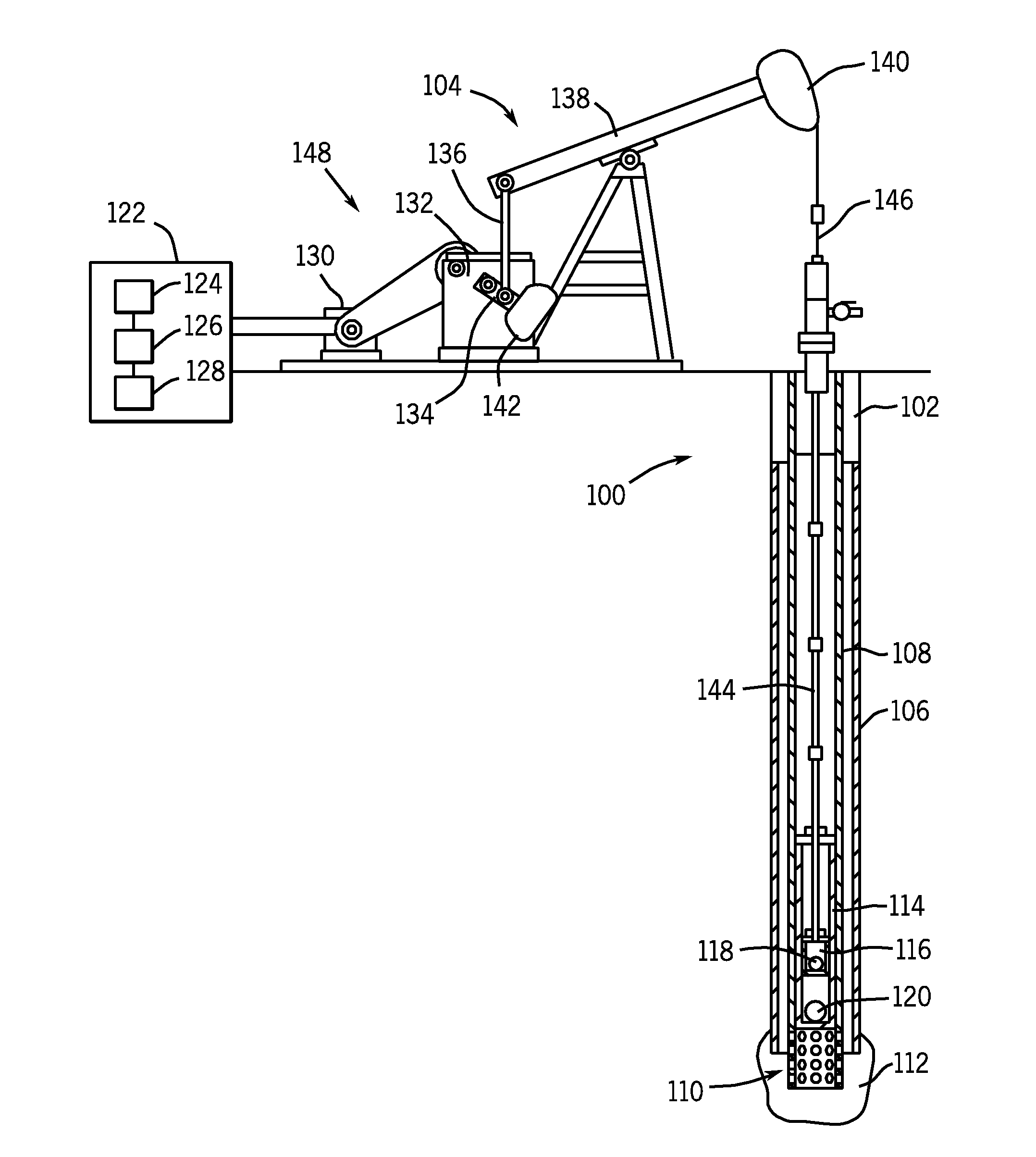
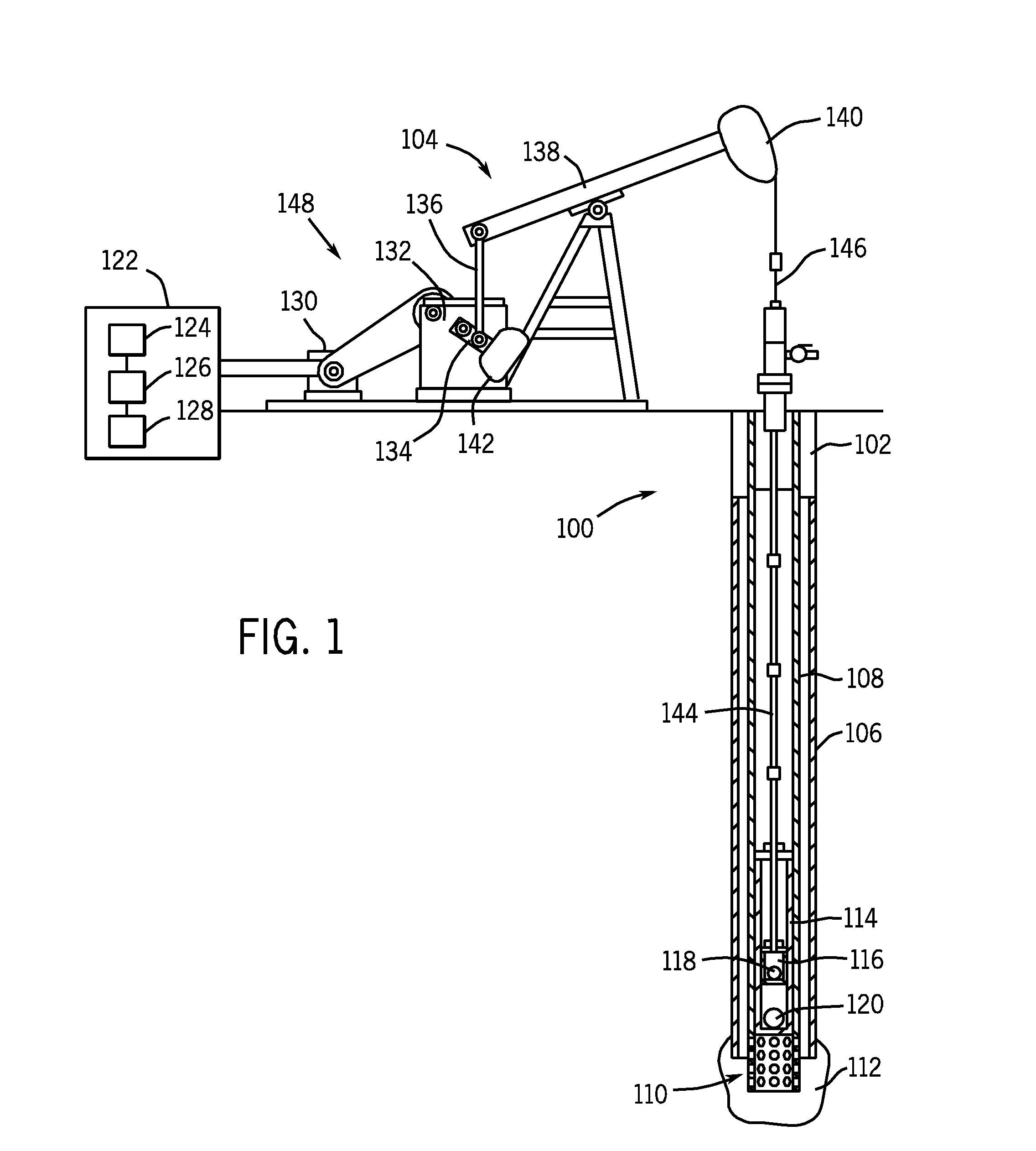
[0029]Sucker rod pumping units are typically driven by an electric motor as the prime mover. In accord with the present disclosure a user is able to determine the crank position of the pumping unit (and therefore the absolute position reference) directly from the prime-mover motor torque and speed (derived from motor current and voltage). Once the absolute position of the crank and main beam are determined, the position of the sucker rod may be subsequently determined using information about the specific pump unit (as described below), where rod position is proportional to the main beam angle times the total rod stroke.

[0030]The preferred embodiment uses a system identification routine during initial calibration (also referred to as commissioning) for identifying the rotary inertia of the system, comprising the crank arm, gearbox, sheaves, and prime-mover motor armature. This routine is initially executed during pump commissioning with an inclinometer (or some other absolute positio...


PUM


Abstract

There is provided a method and system to determine the position of a sucker rod pumping system without a position sensing device during production pumping. A pump control system of the sucker rod pumping system includes a controller coupled to a database, with the controller configured to access an rxless torque value in the database. With the stored rxless torque value representative of toggle points of the crank arm during an initial calibration pumping cycle, the controller further is configured to continuously sample the rxless torque value of the system and determine the crank arm position in relation to the sample rxless torque value. The controller adjusts the pumping system for optimal operations, without a crank arm position sensor during production pumping by identifying a toggle point and setting the crank arm position estimate equal to the value corresponding to the crank position at the identified toggle point.

Description

[0001]CROSS-REFERENCE TO RELATED PATENT APPLICATIONS[0002]This application is a non-provisional application claiming priority to Provisional Application Ser. No. 61 / 722,884 filed Nov. 6, 2012, which is incorporated herein, in its entirely, by this reference.FIELD OF THE INVENTION[0003]The present disclosure relates generally to control of sucker rod pumps for oil, gas, and water wells, and move particularly to an apparatus and methods to determine position of a sucker rod pumping system without a position sensing device during production pumping for optimizing the operation of the rod pump.BACKGROUND OF THE INVENTION[0004]A sucker rod pumping unit reciprocates a rod string to actuate a subterranean pump for the purpose of lifting liquids to the surface. An exemplary embodiment is shown in FIG. 1. Such units are often instrumented with various sensors affixed to the pumping unit for the purpose of tracking pump and well performance. Historically, this instrumentation included sensors...

Claims


Application Information

Patent Timeline
IPC IPC(8): F04C28/00
CPCF04C28/00E21B47/009F04B47/022
Inventor PETERSON, RONALD G.
Owner UNICO LLC
Why Eureka
Try Eureka