Water recovery method
- Summary
- Abstract
- Description
- Claims
- Application Information
AI Technical Summary
Benefits of technology
Problems solved by technology
Method used
Image

Examples
embodiment 1
2. Embodiment 1
(Structure of Water Recovery Device)
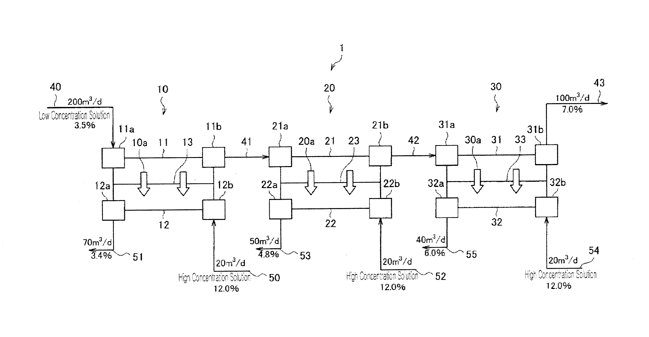
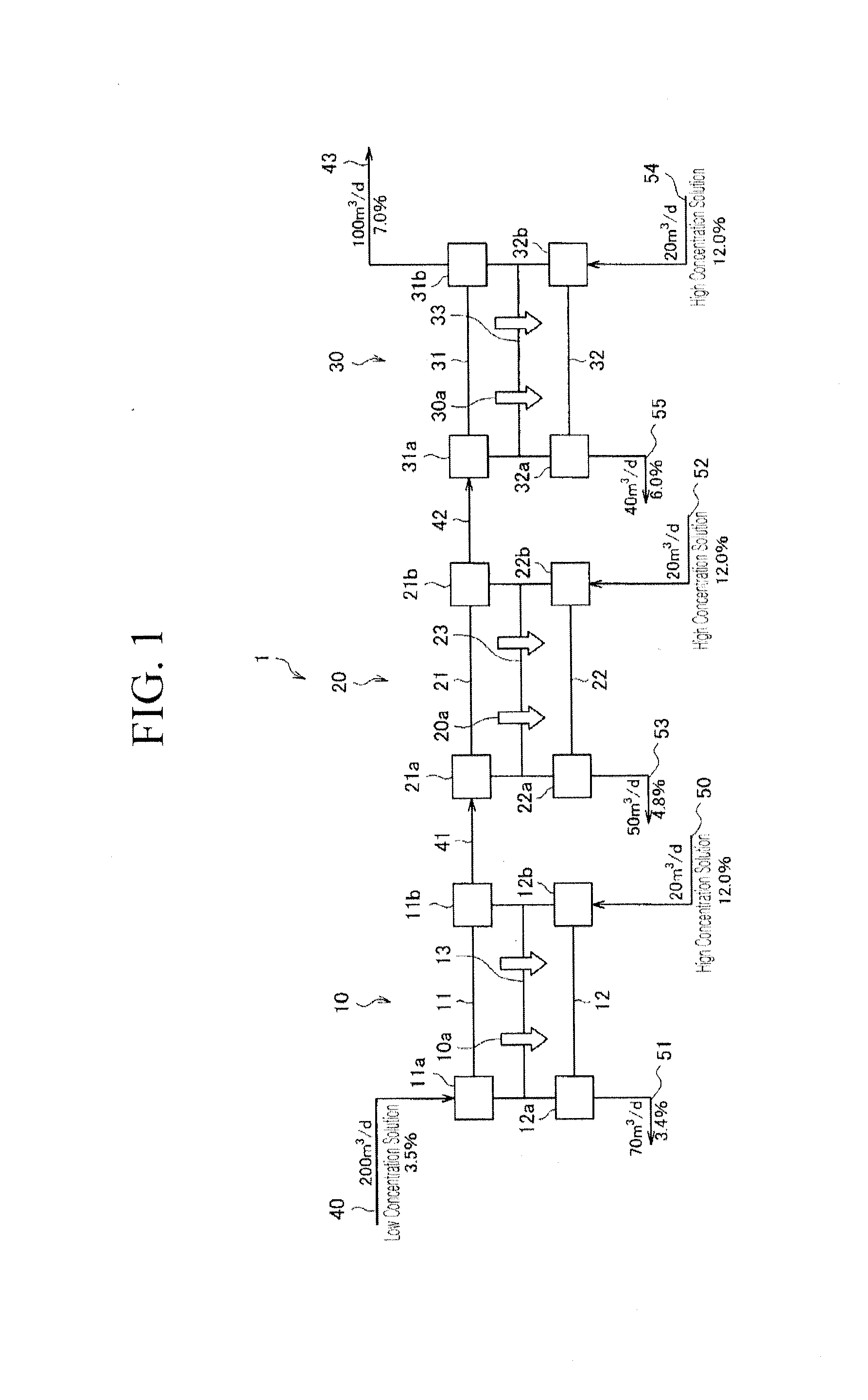
[0080]First, a structure of a water recovery device 1 according to Embodiment 1 is explained referring to FIG. 1.
[0081]The water recovery device 1 schematically includes a flow path for a high concentration solution in parallel compared with a water recovery device 200 shown in FIG. 5.
[0082]More specifically, the water recovery device 1 includes FO membrane modules 10, 20, and 30, connecting flow paths 40, 41, 42, and 43 for a low concentration solution, and connecting flow paths 50, 51, 52, 53, 54, and 55 for a high concentration solution.
[0083]The FO membrane module 10 includes a flow path 11 for a low concentration solution, connectors 11a and 11b for a low concentration solution, a flow path 12 for a high concentration solution, connectors 12a and 12b for a high concentration solution, and an FO membrane 13. The flow path 11 is for distributing a low concentration solution, and the low concentration solution is distributed in th...
embodiment 2
3. Embodiment 2
Structure of Water Recovery Device
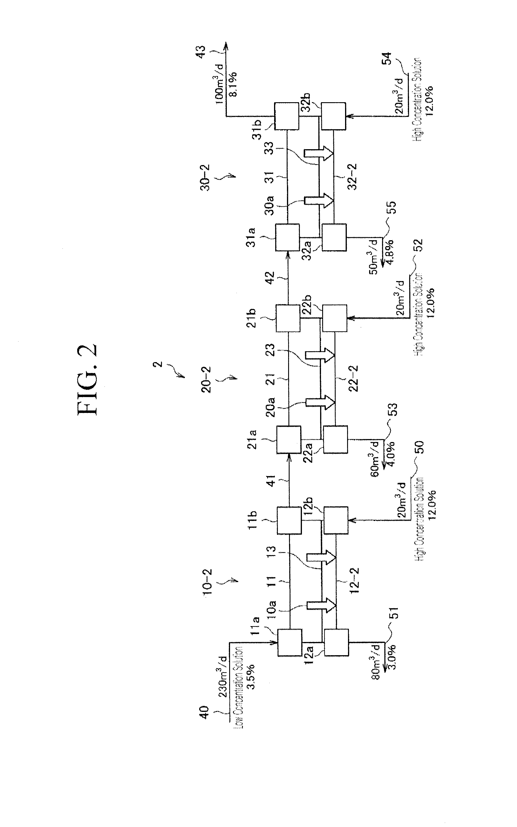
[0154]Referring to FIG. 2, a structure of a water recovery device 2 according to Embodiment 2 is explained.
[0155]The water recovery device 2 includes FO membrane modules 10-2, 20-2, and 30-2 substituted for the FO membrane modules 10, 20, and 30 of the water recovery device 1 according to Embodiment 1.
[0156]The FO membrane modules 10-2, 20-2, and 30-2 include flow paths 12-2, 22-2, and 32-2 substituted for the flow paths 12, 22, and 32 for a high concentration solution of the FO membrane modules 10, 20, and 30.
[0157]The flow paths 12-2, 22-2, and 32-2 for a high concentration solution are narrower than the flow paths 11, 21, and 31 for a low concentration solution. Specifically, the flow paths 12-2, 22-2, and 32-2 for a high concentration solution have narrower vertical cross-sections than those of the flow paths 11, 21, and 31 for a low concentration solution. Accordingly, the flow paths 12-2, 22-2, and 32-2 for a high concentration ...
embodiment 3
4. Embodiment 3
Structure of Water Recovery Device
[0167]Referring to FIG. 3, a structure of a water recovery device 3 according to Embodiment 3 is explained.
[0168]The water recovery device 3 includes FO membrane modules 10-3, 20-3, and 30-3 substituted for the FO membrane modules 10-2, 20-2, and 30-2 in the water recovery device 2 according to Embodiment 2.
[0169]The FO membrane modules 10-3, 20-3, and 30-3 include FO membranes 13-3, 23-3, and 33-3 substituted for the FO membranes 13, 23, and 33 of the FO membrane modules 10-2, 20-2, and 30-2.
[0170]The FO membranes 13-3, 23-3, and 33-3 have a higher permeability coefficient, as the number of steps from an inlet of an in-series flow path for a low concentration solution to the FO membrane module is larger. In other words, the FO membrane 13-3 has the lowest permeability coefficient, and the FO membrane 33-3 has the highest permeability coefficient. That is, the FO membrane module 10 passes water with the most difficulty, and the FO mem...
PUM
 Abstract
Description
Claims
Application Information
PatSnap Eureka turns technology decisions into work you can execute. Powered by our Innovation Knowledge Graph, it runs expert workflows across engineering, life sciences, materials and intellectual property. Get your review-ready output in minutes.


