Antenna tile device and cold plate

a technology of antenna tiles and cold plates, applied in the direction of antennas, antenna details, antenna adaptation in movable bodies, etc., can solve the problems of high level of elevated temperature and heat generation, high loss of rf insertion, and high consumption of power, so as to reduce the loss of insertion, reduce the thickness of the material, and improve the radome radio frequency performance

Active Publication Date: 2014-05-22
VIASAT INC
View PDF3 Cites 25 Cited by
  • Summary
  • Abstract
  • Description
  • Claims
  • Application Information

AI Technical Summary

Benefits of technology

[0009]In another exemplary embodiment, a radome cover is held in contact with an antenna by a negative pressure created inside the radome. A vent connected to a lower pressure side of the radome cover or antenna results in downward pressure on the radome and pushes the radome into direct contact with the structure of the antenna. The radio frequency (RF) performance of the radome can be improved by reducing the material thickness and thus reduce RF insertion losses. In an exemplary embodiment, a reduction in the radome's structural stiffness is negated by the structural support provided by the antenna structure.

Problems solved by technology

However, the phased array comprises several electrical circuits that consume a substantial amount of power during operation.
This in turn results in a high level of elevated temperature and generation of heat.
Additionally, due to space limitations, various elements are located off the integrated circuit chip.
The plug radiators and extra couplings often times introduce losses, larger footprint, more hardware to malfunction, and greater cost.
Furthermore, the historical phased array aperture antenna systems are not able to dynamically electronically control polarization and / or vector of the unit antenna tile.

Method used


Image

  • Antenna tile device and cold plate
  • Antenna tile device and cold plate
  • Antenna tile device and cold plate

Examples


Embodiment Construction

[0028]While exemplary embodiments are described herein in sufficient detail to enable those skilled in the art to practice the invention, it should be understood that other embodiments may be realized and that logical electrical and mechanical changes may be made without departing from the spirit and scope of the invention. Thus, the following detailed description is presented for purposes of illustration only.

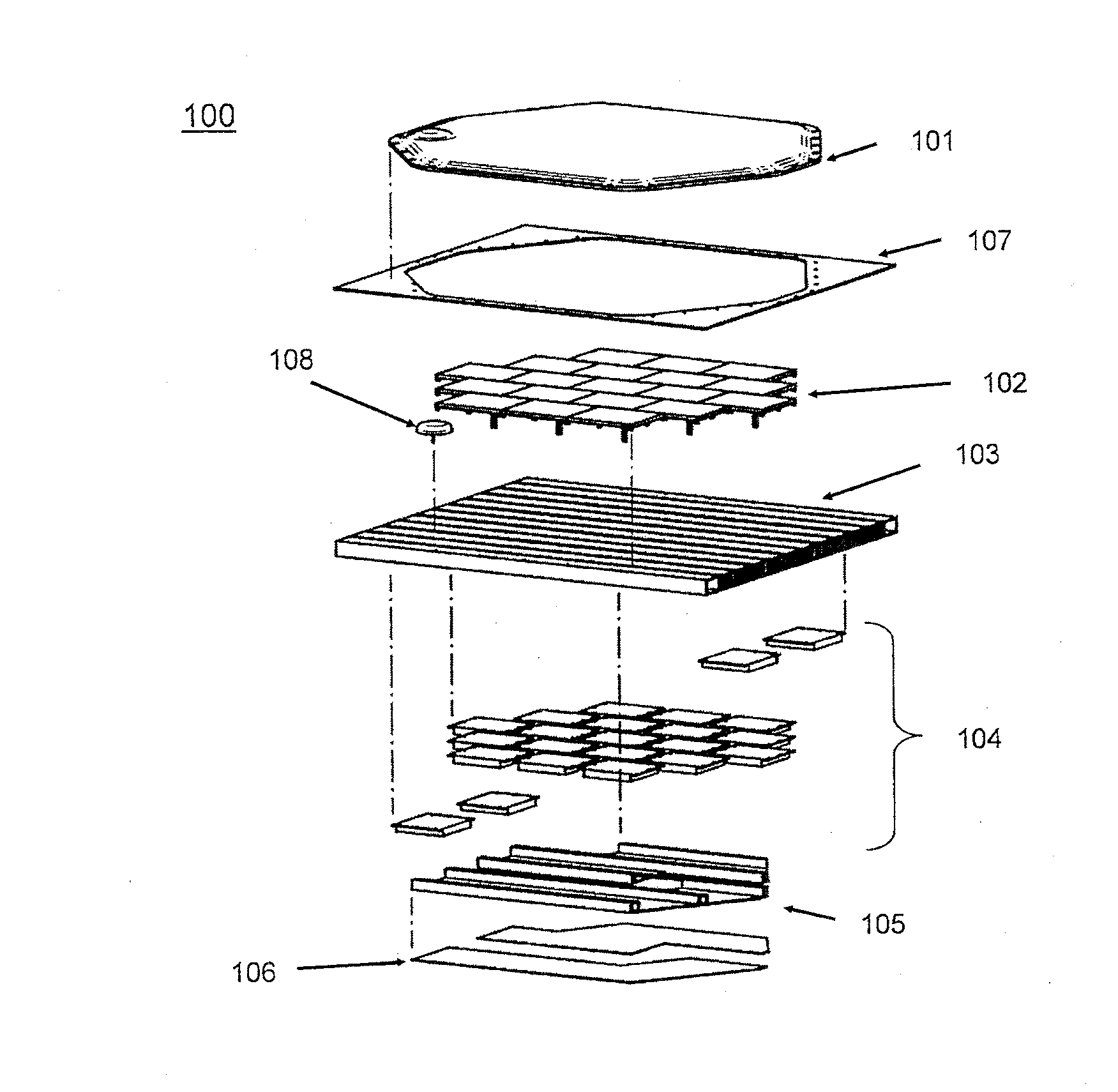
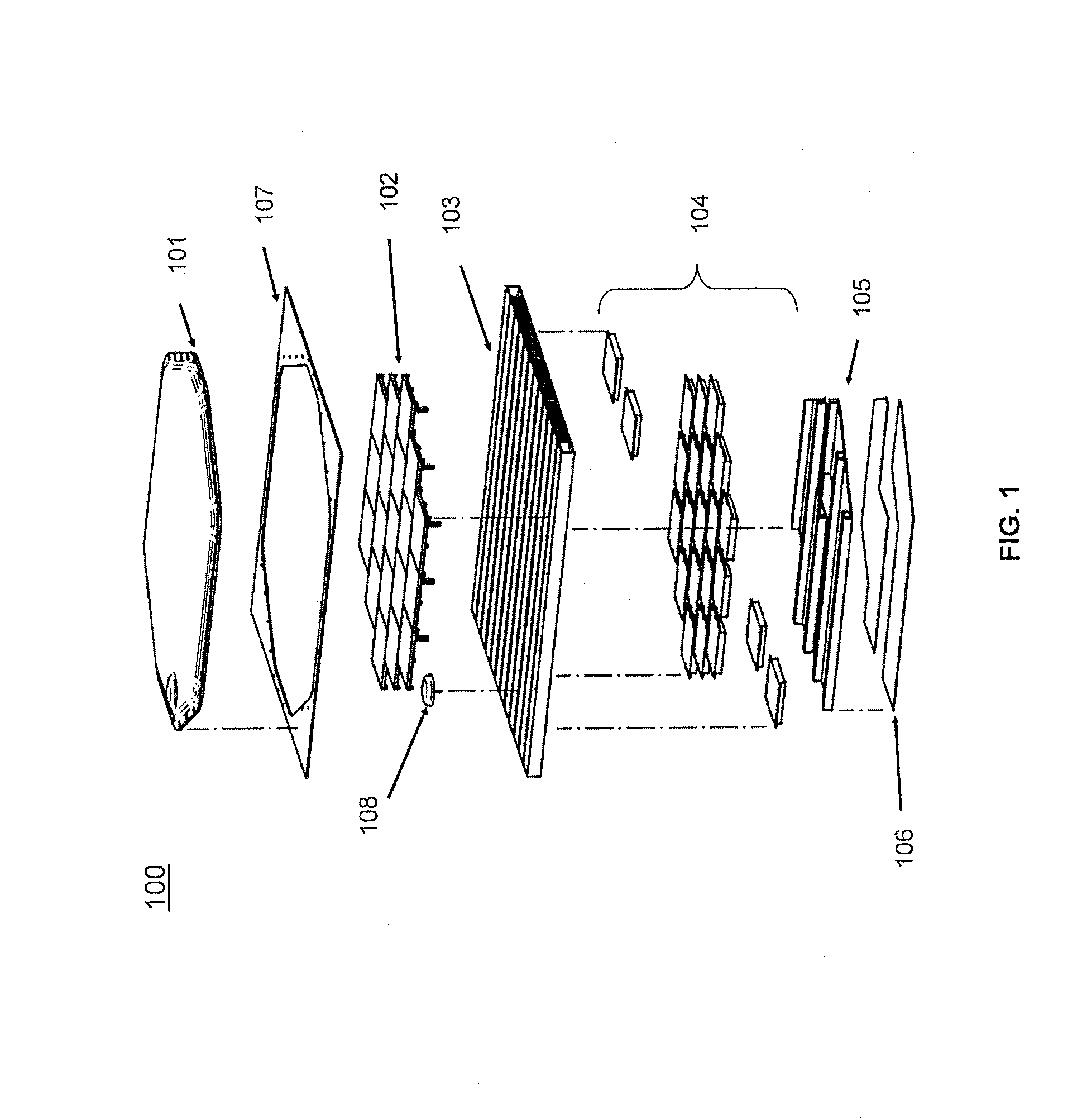
[0029]With reference to the detailed assembly shown in FIG. 1, in an exemplary embodiment, a phased array antenna 100 comprises a radome 101, multiple aperture tiles 102, a cold plate 103, and multiple electrical components 104. Furthermore, in an exemplary embodiment, the multiple electrical components 104 comprise at least one electronics power converter, at least one broadband up-down converter, at least one time delay and control unit, and multiple tile power converters. In another exemplary embodiment, phased array antenna 100 further comprises a printed circuit board (PC...


PUM


Abstract

A method, system, and device relating to a broad-band fragmented aperture tile and antenna system are disclosed. In one exemplary embodiment, an aperture tile comprises a plurality of unit cells. The plurality of unit cells individually comprise a driven radiating element layer, a module layer having a printed circuit board, wherein the module layer comprises one or more of a time delay module, a radio frequency distribution module, a radio frequency module, or a digital signal processor. Furthermore the aperture tile is coupled to a cold plate configured for heat transfer.

Description

CROSS REFERENCE TO RELATED APPLICATIONS[0001]This application is a continuation of U.S. application Ser. No. 12 / 916,380, entitled “ANTENNA TILE DEVICE AND COLD PLATE,” which was filed on Oct. 29, 2010. The '380 application is a non-provisional of U.S. Provisional Application No. 61 / 256,820, entitled “PASSIVE AIR COOLED ANTENNA SYSTEM,” which was filed on Oct. 30, 2009. The '380 application is also a non-provisional of U.S. Provisional Application No. 61 / 265,596, entitled “ANTENNA TILE DEVICE AND DESIGN,” which was filed on Dec. 1, 2009. All of the contents of the previously identified applications are hereby incorporated by reference for any purpose in their entirety.FIELD OF INVENTION[0002]The application relates to systems, devices, and methods for an antenna tile. More particularly, the application relates to a broad-band fragmented aperture printed circuit board antenna tile for use in a phased array antenna system. Furthermore, the application relates to systems, devices, and m...

Claims


Application Information

Patent Timeline
Patent Type & Authority Applications(United States)
IPC IPC(8): H01Q1/02
CPCH01Q1/02H01Q1/28H01Q21/065
Inventor VOSS, JOHN DANIELRUNYON, DONALD LAWSON
Owner VIASAT INC
Why Eureka
Try Eureka