Adjustable Spinal Implant Insertion Instrument

Active Publication Date: 2014-05-22
K2M
View PDF6 Cites 11 Cited by
  • Summary
  • Abstract
  • Description
  • Claims
  • Application Information

AI Technical Summary

Benefits of technology

[0013]In an embodiment for the system for inserting a spinal implant into an intervertebral space with an insertion instrument, the system includes the insertion instrument and the spinal implant discussed above. The trailing end of the spinal implant configured to cooperate with the distal end of the holdin

Problems solved by technology

Excessive pressure or injuries to the intervertebral discs may adversely affect the annulus fibrosus.
The annulus fibrosus may be injured in several ways.
The formation of scar tissue may eventually lead to damage to the nucleus pulposus.
As a result of this damage, the nucleus fibrosus may, for instance, lose water content, hindering

Method used


Image

  • Adjustable Spinal Implant Insertion Instrument
  • Adjustable Spinal Implant Insertion Instrument
  • Adjustable Spinal Implant Insertion Instrument

Examples


Example

[0034]Particular embodiments of the present disclosure will be described herein with reference to the accompanying drawings. As shown in the drawings and as described throughout the following description, and as is traditional when referring to relative positioning on an object, the term “proximal” or “trailing” refers to the end of the apparatus that is closer to the user and the term “distal” or “leading” refers to the end of the apparatus that is farther from the user. In the following description, well-known functions or constructions are not described in detail to avoid obscuring the present disclosure in unnecessary detail.

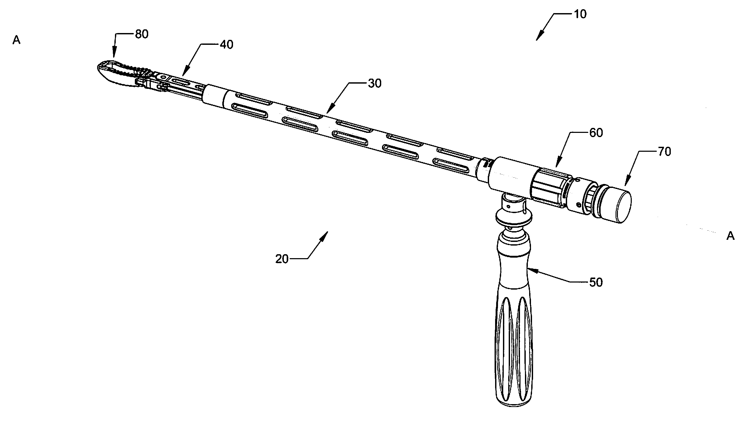
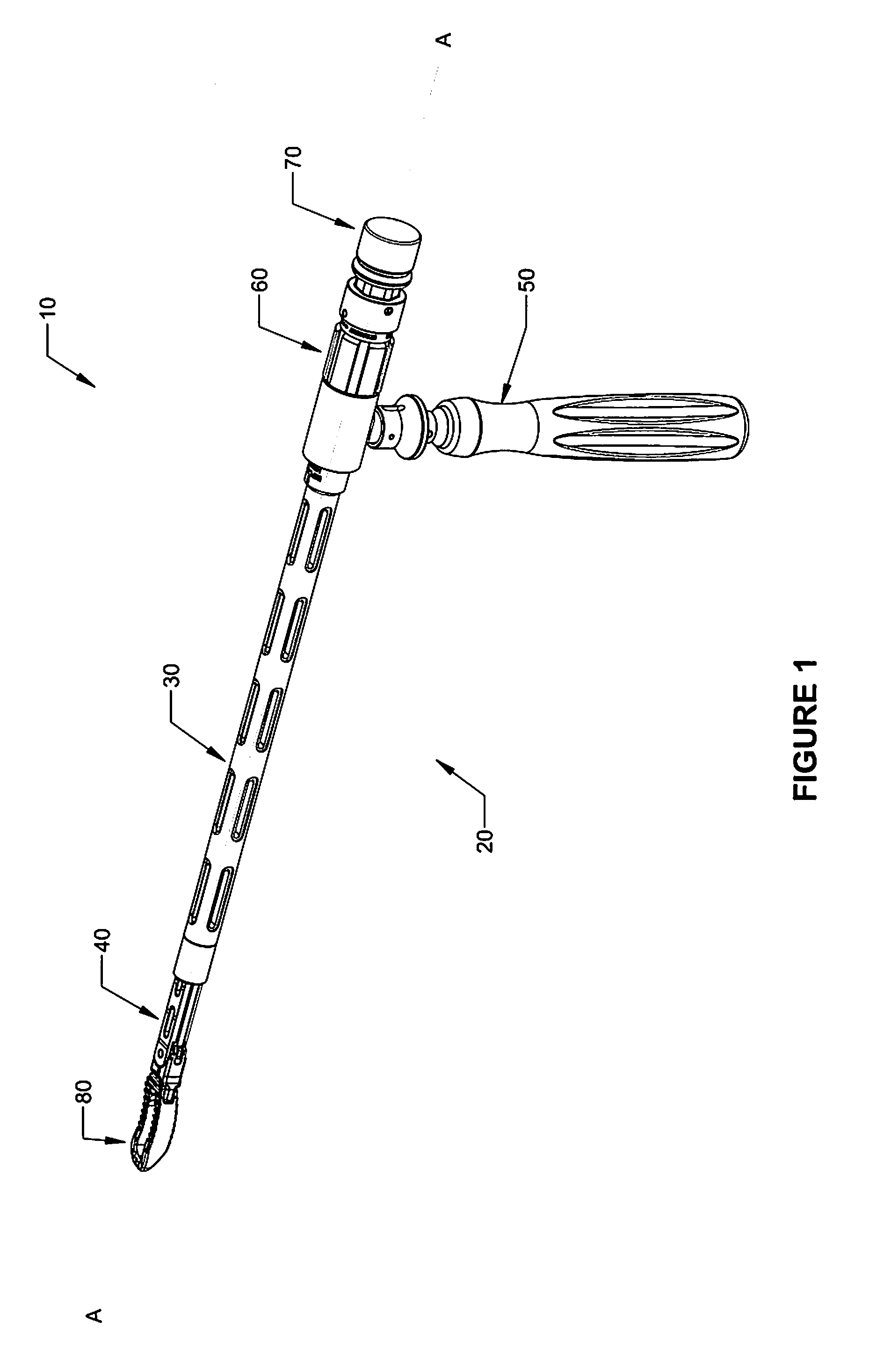
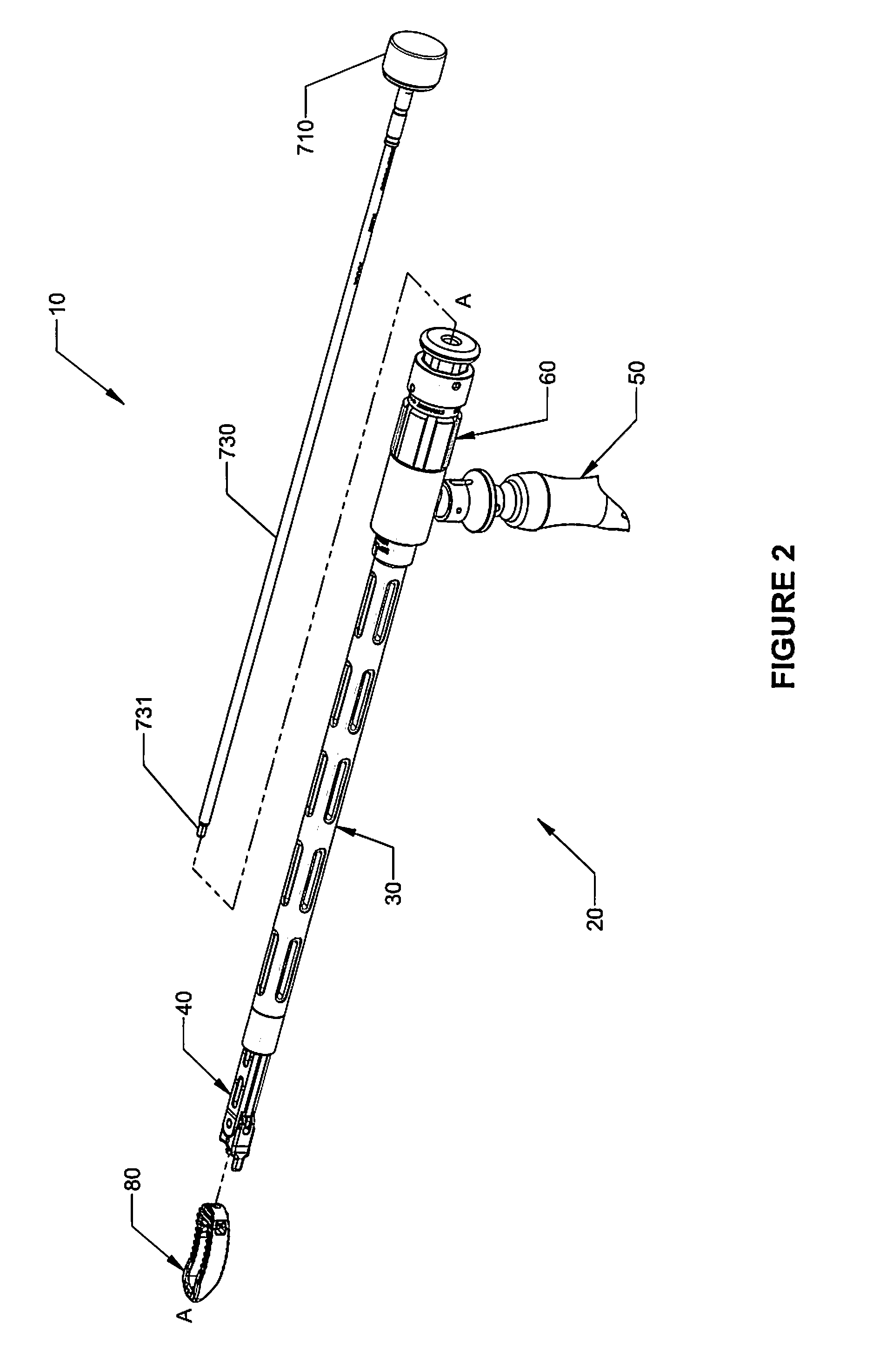
[0035]Referring now to the drawings, in which like reference numerals identify identical or substantially similar parts throughout the several views, FIGS. 1 and 2 illustrate an embodiment of system 10 for inserting a spinal implant into an intervertebral space with an insertion instrument.

[0036]The embodiment of insertion instrument 20 shown in FIG. 3 inclu...


PUM


Abstract

An instrument for inserting a spinal implant into an intervertebral space is disclosed. The instrument includes an elongated body having inner and outer shafts configured to longitudinally translate with respect to each other, a holding tip which is configured to articulate with respect to the elongated body in response to the longitudinal translation of the inner and outer shafts, and a driveshaft assembly configured to cooperate with the articulation of the holding tip and secure a spinal implant to the instrument. A spinal implant and a system for inserting a spinal implant into an intervertebral space including an insertion instrument and a spinal implant are also disclosed.

Description

BACKGROUND[0001]1. Technical Field[0002]The present disclosure relates to apparatus and systems for orthopedic spine surgery and, in particular, to an apparatus for inserting a spinal implant into an intervertebral space.[0003]2. Description of Related Art[0004]The human spine is comprised of thirty-three vertebrae and twenty-four as an adult. An infant contains 7 cervical vertebrae, 12 dorsal or thoracic vertebrae, 5 lumbar vertebrae, 5 sacral vertebrae, and 4 coccygeal or caudal vertebrae. In an adult, the 5 sacral vertebrae fuse together to form the sacrum and the 4 coccygeal vertebrae fuse to form the coccyx. Intervertebral discs lie between each pair of adjacent vertebrae. Every intervertebral disc maintains a space between adjacent vertebrae and acts as cushion under compressive, bending, and rotational loads and motions. Each intervertebral disc has a fibrocartilaginous central portion called the nucleus pulposus. The nucleus pulposus of a healthy intervertebral disc contains...

Claims


Application Information

Patent Timeline
IPC IPC(8): A61B17/70
CPCA61B17/7074A61F2/4465A61F2/4611A61F2002/30795A61F2002/30797A61F2002/30904A61F2002/4627A61F2002/4628A61F2002/4629A61F2/4603A61F2002/30593
Inventor WALLENSTEIN, TODDMIZ, GEORGEWILLIAMS, JOHN I
Owner K2M
Why Eureka
Try Eureka