
Apparatus and method for space-division multiplexing optical coherence tomography

a technology of optical coherence tomography and optical coherence, applied in the field of tomography, can solve the problems of not having a commercially available wavelength tunable laser or high-speed line-scan camera that operates at that speed, and achieve the effect of improving imaging speed

Active Publication Date: 2014-06-12
LEHIGH UNIVERSITY
View PDF2 Cites 69 Cited by
  • Summary
  • Abstract
  • Description
  • Claims
  • Application Information

AI Technical Summary

Benefits of technology

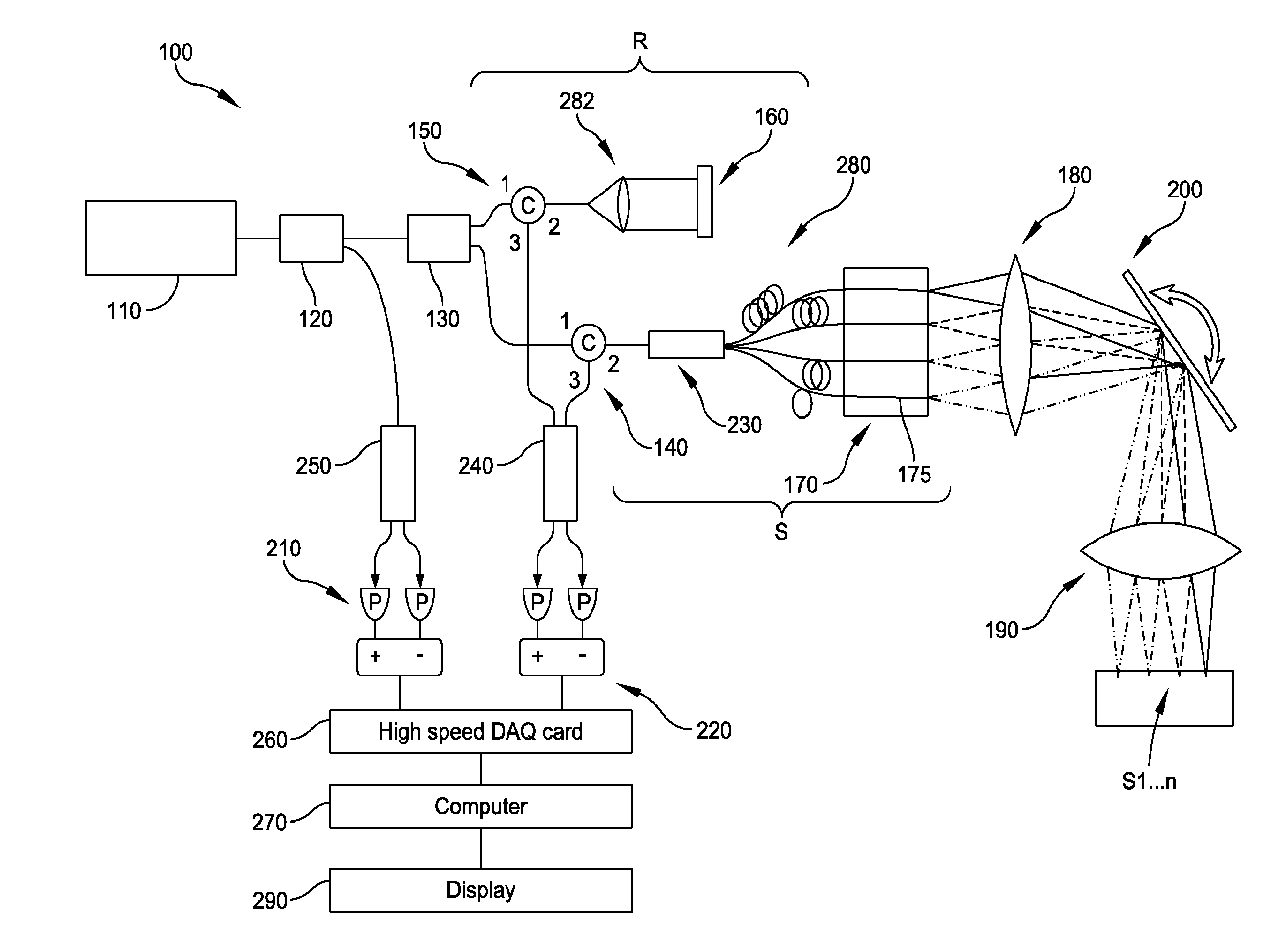
This patent is about an optical coherence tomography (OCT) system that use a wavelength tunable light source to improve imaging speed and depth range. The system takes advantage of the long coherence length property of these light sources to achieve an order of magnitude improvement in effective A-line rate. The system can also utilize parallel detection of spatially distributed optical beams to further improve imaging speed. With this system, OCT imaging becomes faster, while maintaining resolution and sensitivity. The system also enables synchronized simultaneous imaging at multiple sample locations using multiple beams, which opens up opportunities for numerous biomedical applications.

Problems solved by technology

However, currently there is no commercially-available wavelength tunable laser or high speed line-scan camera that operates at that speed.

Method used


Image

  • Apparatus and method for space-division multiplexing optical coherence tomography
  • Apparatus and method for space-division multiplexing optical coherence tomography
  • Apparatus and method for space-division multiplexing optical coherence tomography

Examples


Embodiment Construction

[0033]The features and benefits of the invention are illustrated and described herein by reference to preferred embodiments. Accordingly, the invention expressly should not be limited to such preferred embodiments illustrating some possible non-limiting combination of features that may exist alone or in other combinations of features; the scope of the invention being defined by the claims appended hereto. This description of preferred embodiments is intended to be read in connection with the accompanying drawings, which are to be considered part of the entire written description. The drawing figures are not necessarily to scale and certain features may be shown exaggerated in scale or in somewhat schematic form in the interest of clarity and conciseness. Accordingly, size, thicknesses, and spacing of various layers of materials or structures shown in the accompanying drawings are not limited to the relative sizes, thicknesses, or spacing shown in the accompanying drawings.

[0034]In t...


PUM


Abstract

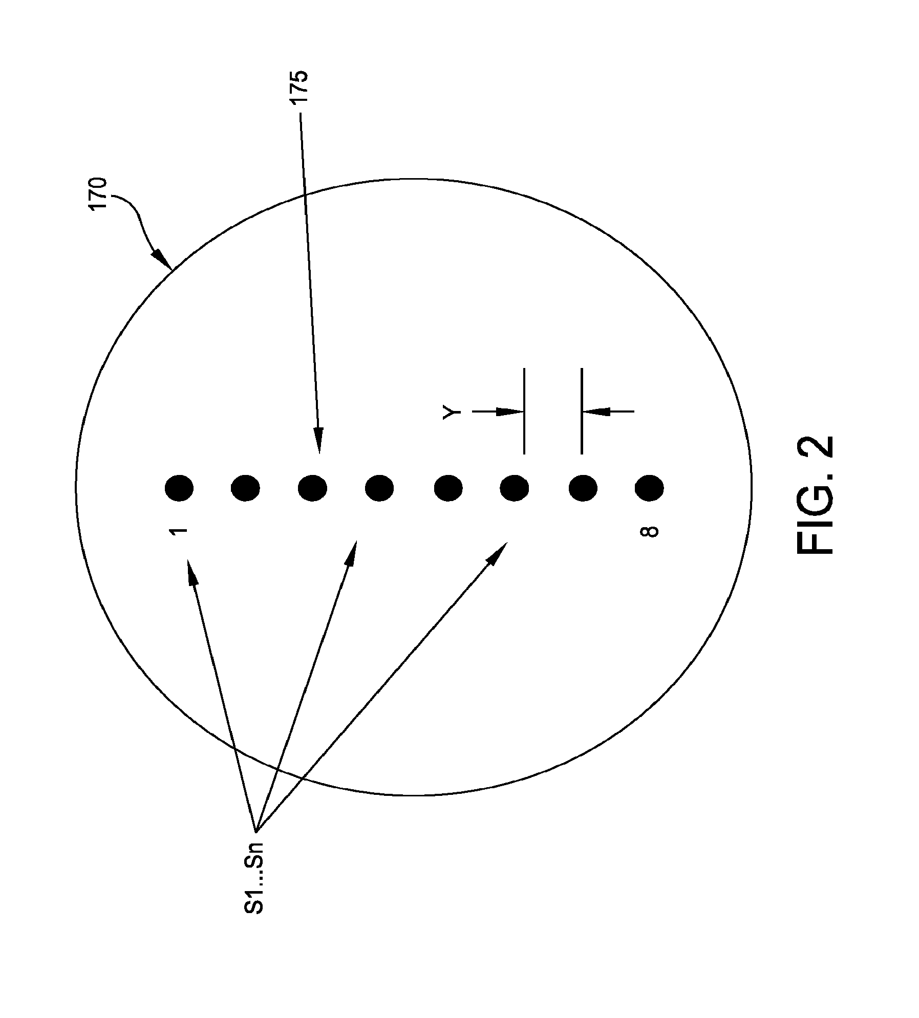
A space-division multiplexing optical coherence tomography apparatus and system is provided. In one embodiment, the system includes a light source, a reference arm, and a sample arm. The sample arm splits the sampling light into a plurality of sampling beams which may be scanned simultaneously onto a surface of a sample. An optical delay may be introduced into the sampling beams before scanning. A plurality of reflected light signals returned from the sample is collected. In one arrangement, the signals may be combined to produce a single reflected light signal. The reflected light signal(s) and a reference signal are combined to produce an interference signal comprising data representative of digitized images captured of the actual object. In one embodiment, a single sample arm may be used for scanning and collecting image data. A related method is also provided.

Description

CROSS REFERENCE TO RELATED APPLICATIONS[0001]The present application claims the benefit of priority to U.S. Provisional Patent Application No. 61 / 734,168 filed Dec. 6, 2012, and U.S. Provisional Patent Application No. 61 / 819,251 filed May 3, 2013; the contents of which are both incorporated herein by reference in their entireties.STATEMENT OF GOVERNMENT INTEREST[0002]This invention was made with government support under R00-EB010071 awarded by National Institutes of Health (NIH)-National Institute of Biomedical Imaging and Bioengineering (NIBIB). The government has certain rights in the invention.FIELD OF DISCLOSURE[0003]The present disclosure relates to tomography, and more particularly to optical coherence tomography.BACKGROUND OF THE DISCLOSURE[0004]Optical coherence tomography (OCT) is an emerging optical imaging technique that enables micron-scale, cross-sectional, and three-dimensional (3D) imaging of biological tissues in situ and in real-time. OCT functions as a type of “opt...

Claims


Application Information

Patent Timeline
Patent Type & Authority Applications(United States)
IPC IPC(8): G01B9/02
CPCG01B9/02091A61B5/0066G01B9/02004G01B9/02019G01B9/02028G01B9/02041
Inventor ZHOU, CHAO
Owner LEHIGH UNIVERSITY
Learn More