Articulated Bed-Mounted Finned-Spar-Buoy Designed for Current Energy Absorption & Dissipation

a technology of current energy absorption and dissipation, which is applied in the direction of stream regulation, special-purpose vessels, transportation and packaging, etc., can solve the problems of buoy motions that become unstable at certain current speeds, ship handling and shoreline erosion, and navigation problems, so as to prevent the drift of sand bars

Active Publication Date: 2014-06-12
MURTECH
View PDF3 Cites 8 Cited by
  • Summary
  • Abstract
  • Description
  • Claims
  • Application Information

AI Technical Summary

Benefits of technology

[0013]A method for reducing the energy in a stream or river current is disclosed. The method comprises: locating a plurality of buoys upstream of an object that is at least partially submerged and exposed to the stream or river current (e.g., a piling, a sand bar, etc.); anchoring the plurality of buoys to a bed in the stream or river; and permitting the plurality of buoys to pivot about the anchor due to exposure of the plurality of buoys within the stream or river that causes buoy movement and vortex shedding, thereby dissipating energy of the stream or river current.
[0014]A buoy array for reducing the energy in a stream or river current is disclosed. The buoy array comprises: a plurality of buoys that are disposed at a predetermined distance from one another upstream of an object that is at least partially submerged and exposed to the stream or river current (e.g., a piling, a sand bar, etc.), and wherein the plurality of buoys is positioned transversely of the stream or river current, and wherein each one of the plurality of buoys comprises: an elongated cylindrical body with a plurality of vertically-oriented fins protruding radially away from an outer surface of the body; and wherein each of the bodies comprises a center staff that is coupled to a hinge and each of the hinges is coupled to the stream or river bed, wherein the hinge permits the body to freely rotate about the hinge when each of the bodies are exposed within the stream or river that causes buoy movement and vortex shedding, thereby absorbing and dissipating energy of the stream or river current.

Problems solved by technology

For many years, strong river and tidal currents have posed problems in navigation, ship handling and shoreline erosion.
The navigation problem in rivers stems from the fact that the currents cause bed erosion up-river and accretion down-river.
These fast-water buoys have two major problems.
The first is that the buoy motions become unstable at certain current speeds, as described by McCormick and Folsom (1973) and others.
The second problem is that the buoys are subject to mooring failures caused by fatigue or collisions with passing vessels.

Method used


Image

  • Articulated Bed-Mounted Finned-Spar-Buoy Designed for Current Energy Absorption & Dissipation
  • Articulated Bed-Mounted Finned-Spar-Buoy Designed for Current Energy Absorption & Dissipation
  • Articulated Bed-Mounted Finned-Spar-Buoy Designed for Current Energy Absorption & Dissipation

Examples


example

[0093]Sand bars in the Mississippi-Missouri river system pose navigation problems for the mariners on the rivers. As stated earlier, these bars are normally marked by fast-water buoys by the U. S. Coast Guard. Unfortunately, these buoys are at times lost due to either boat collisions or extreme flow events. In addition, the bars appear, disappear and migrate near river bends. As a result, a fast-water buoy might be at a site formerly occupied by a bar. The new position of the bar would, then, be unmarked and, as a result, the bar would be a navigation hazard.

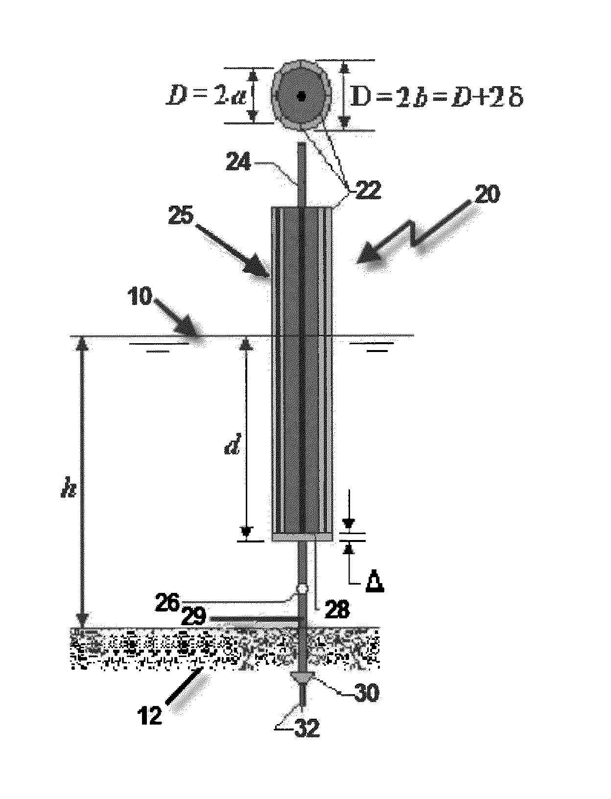
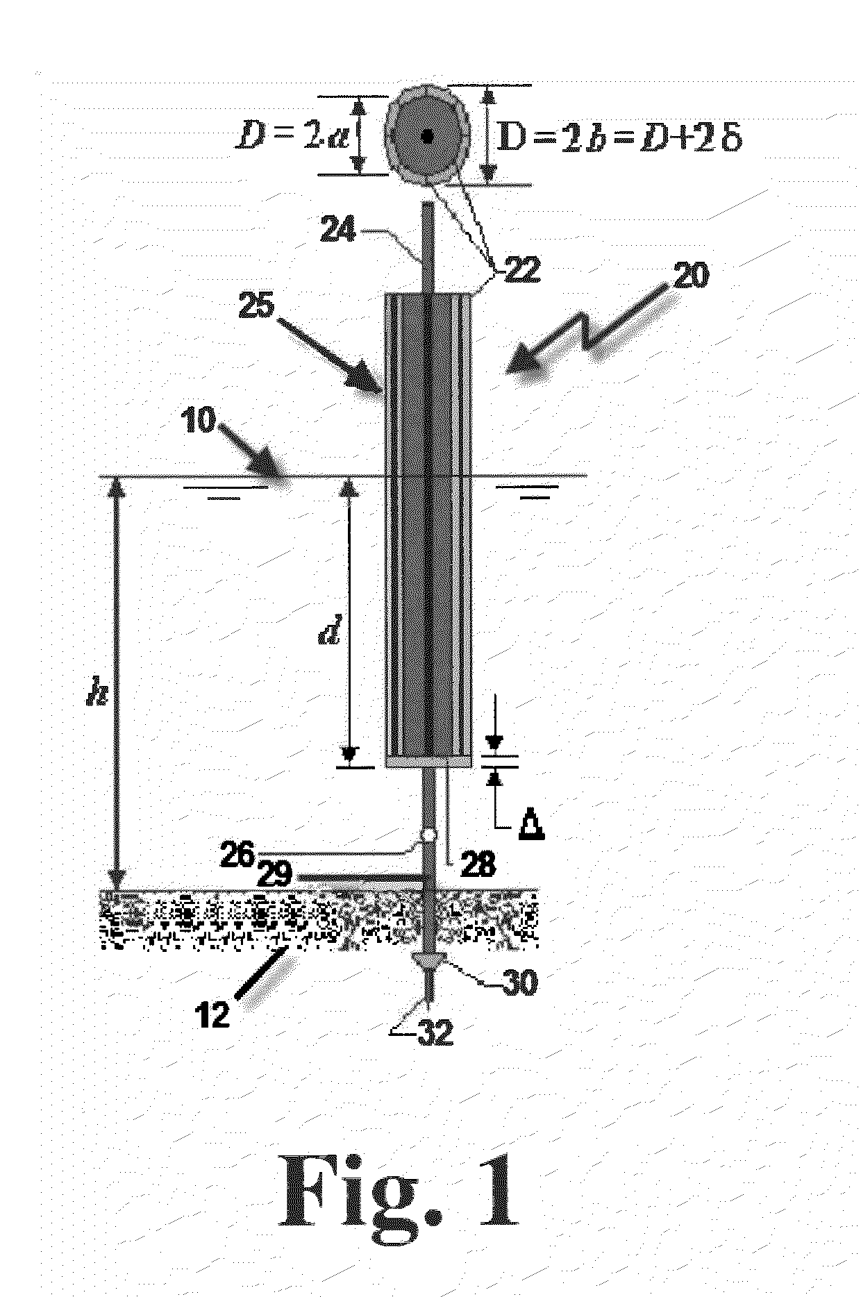
[0094]In the Mississippi-Missouri river system, the approximate nominal current range is from 3 ft / s to 10 ft / s. Consider the deployment of an 8-fin FSB in 6 feet of water, where the current is uniform from the bed to the free surface. Referring to the sketch in FIG. 1, the draft (d) of the FSB is 5.5 ft, and the spring-loaded hinge is at z=−R=−6 ft. That is, the point of rotation is on the bed. The free-board of the FSB is 3 ft...


PUM


Abstract

A constrained buoy experiencing vortex-induced, in-line and transverse angular motions and designed to absorb and attenuate the energies of streams, rivers and localized ocean currents is described. Referred to as a Finned-Spar-Buoy (FSB), the buoy design can be considered an exoskeleton, in that vertical fins are externally mounted on a vertical cylindrical float. The fins increase the drag coefficient by enhancing the wake losses. The FSB operates as a single unit or as a component of an array, depending on the application. The FSB can adjust to high-water events caused by tides, storm surges or spring-melting runoffs because the FSB can move axially along a center-staff which is attached to an anchor pole at a pivot point. The buoy-staff system is allowed to rotate in any angular direction from the vertical, still-water orientation of the center-staff. The FSB has a relatively small diameter-to-draft ratio, analytically qualifying the buoy as a slender-body.

Description

STATEMENT REGARDING FEDERALLY SPONSORED RESEARCH OR DEVELOPMENT[0001]“Not Applicable”FIELD OF THE INVENTION[0002]This invention relates generally to floating systems including at least one buoy arranged to absorb and attenuate the energies of streams, rivers and localized ocean currents, and thus stabilize underwater sand bars.BACKGROUND OF THE INVENTION[0003]For many years, strong river and tidal currents have posed problems in navigation, ship handling and shoreline erosion. The navigation problem in rivers stems from the fact that the currents cause bed erosion up-river and accretion down-river. The current, then, causes the accreted beds to meander. This is particularly true on the Mississippi River system, where bars appear at bends and, then, disappear. The U. S. Coast Guard has been responsible for marking these meandering bars. In order to warn mariners of the presence of sand bars, fast-water buoys have been deployed by the Coast Guard. These fast-water buoys have two major...

Claims


Application Information

Patent Timeline
Patent Type & Authority Applications(United States)
IPC IPC(8): E02B3/02
CPCE02B3/062E02B3/04B63B22/16E02B3/02
Inventor MCCORMICK, MICHAEL E.MURTHA, ROBERT
Owner MURTECH
Why Eureka
Try Eureka