Air-conditioning apparatus for vehicle

a technology for air-conditioning apparatus and vehicle, which is applied in the direction of vehicle heating/cooling devices, machine using electric/magnetic effects, refrigerant needs improvement, and air-conditioning system using cooling water and thermoelectric devices are still at the rudimentary level, so as to achieve optimal heat control, prevent waste of energy, and reduce waste heat

Active Publication Date: 2014-06-19
HYUNDAI MOTOR CO LTD +1
View PDF13 Cites 7 Cited by
  • Summary
  • Abstract
  • Description
  • Claims
  • Application Information

AI Technical Summary

Benefits of technology

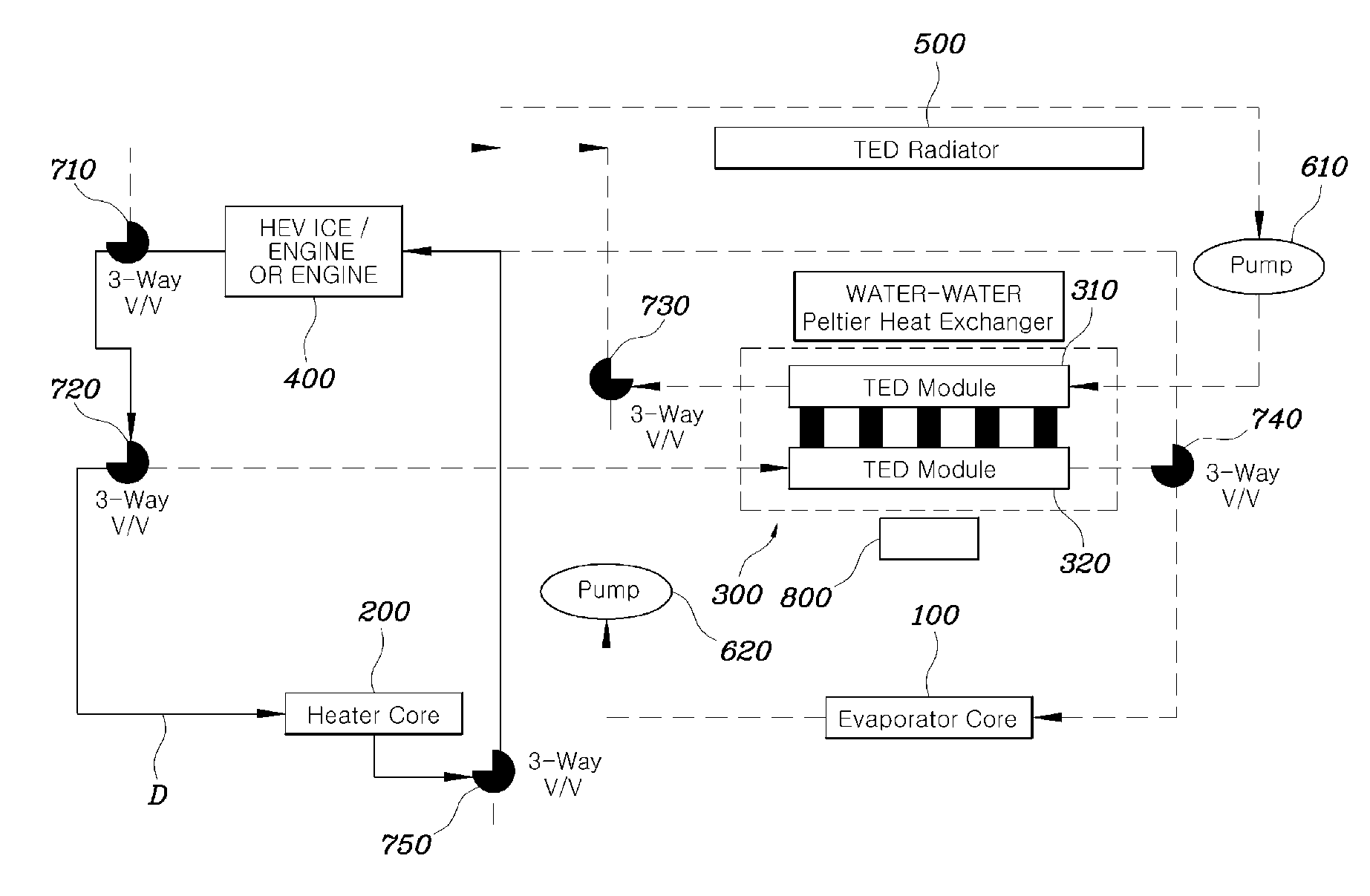
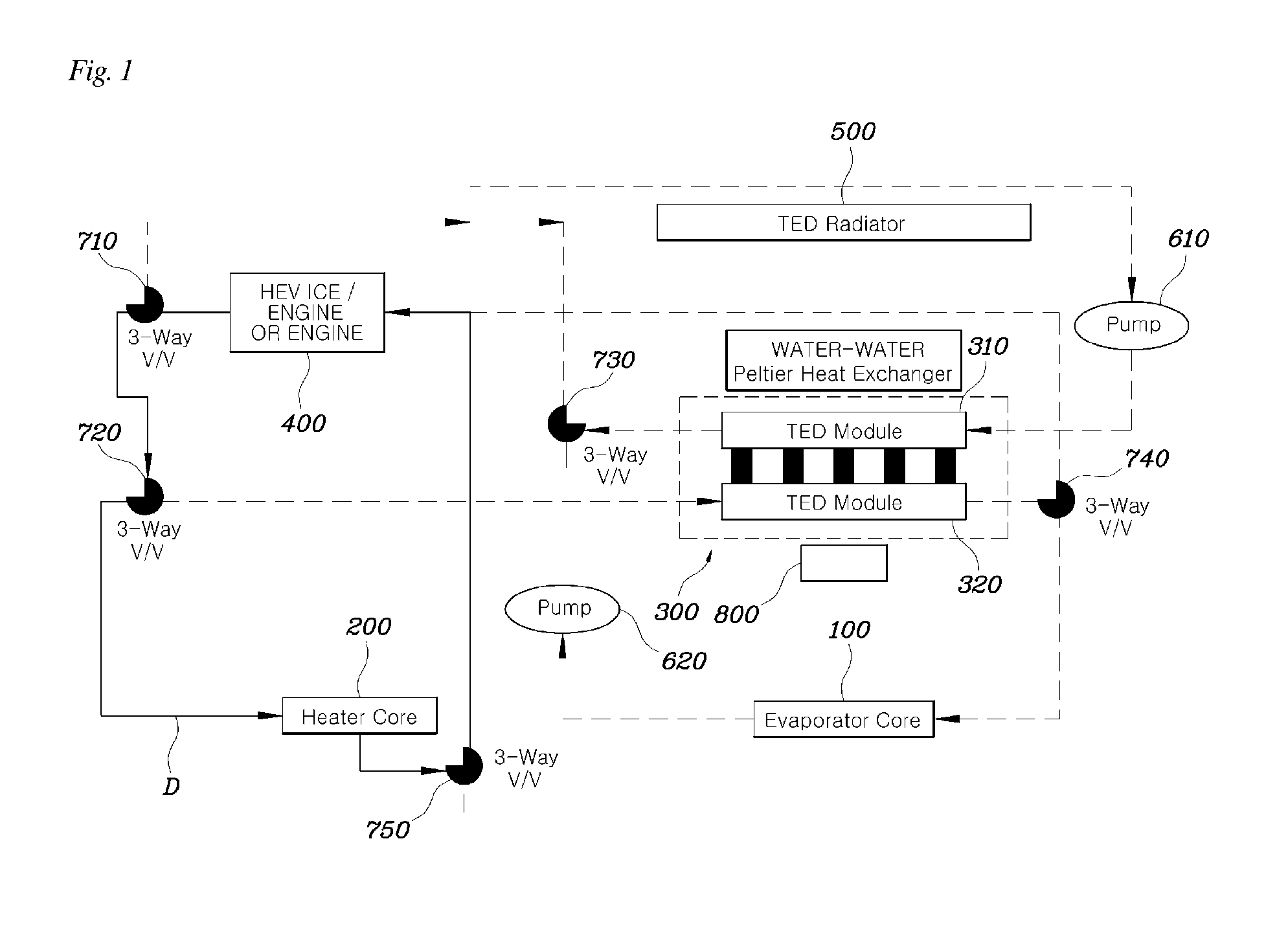
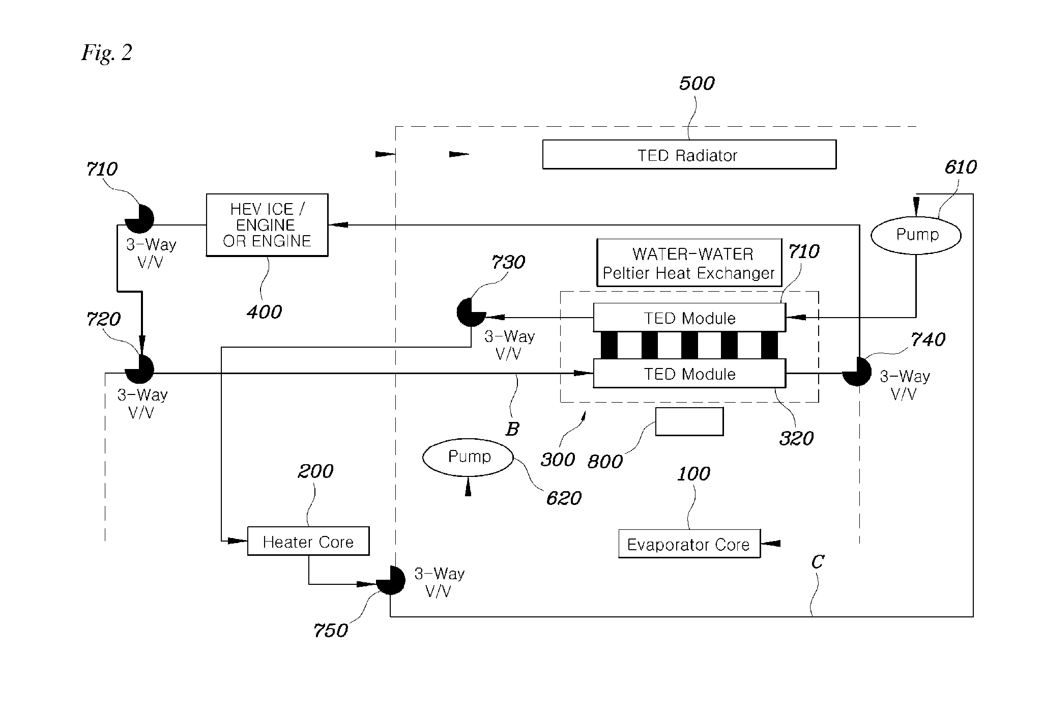
[0016]According to the air-conditioning apparatus having the above-mentioned configuration, both an air-conditioning system and a vehicle cooling system can be operated together using only the cooling water with a refrigerant removed from an existing refrigerant-based air-conditioning apparatus. As a result, the refrigerant is replaced with the cooling water to impart environmental effects. Furthermore, an air-conditioning system for an interior of the vehicle as well as the cooling system for an engine is provided, and optimized heat control is performed by a compact system. Thereby, waste heat can be reduced, and waste of energy can be prevented.

Problems solved by technology

However, the use of refrigerant has added to the effects on global warming Air conditioning systems (including a hot gas system) using the refrigerant require mechanical power, convert electrical energy into mechanical energy, and perform heating and cooling.
Thus, mechanical loss as well as quality issues caused by mechanical parts and leakage of the refrigerant are in need of improvement.
However, even on the basis of this technology, an air-conditioning system using cooling water and the thermoelectric device is still only at its rudimentary level.
As such, there is a problem associated with the overall heat control of a vehicle, a new system capable of replacing both an existing air-conditioning system and an existing heat-radiating system has yet to be proposed.

Method used


Image

  • Air-conditioning apparatus for vehicle
  • Air-conditioning apparatus for vehicle
  • Air-conditioning apparatus for vehicle

Examples


Embodiment Construction

[0022]It is understood that the term “vehicle” or “vehicular” or other similar term as used herein is inclusive of motor vehicles in general such as passenger automobiles including sports utility vehicles (SUV), buses, trucks, various commercial vehicles, watercraft including a variety of boats and ships, aircraft, and the like, and includes hybrid vehicles, electric vehicles, combustion, plug-in hybrid electric vehicles, hydrogen-powered vehicles and other alternative fuel vehicles (e.g. fuels derived from resources other than petroleum).

[0023]The terminology used herein is for the purpose of describing particular embodiments only and is not intended to be limiting of the invention. As used herein, the singular forms “a”, “an” and “the” are intended to include the plural forms as well, unless the context clearly indicates otherwise. It will be further understood that the terms “comprises” and / or “comprising,” when used in this specification, specify the presence of stated features,...


PUM


Abstract

An air-conditioning apparatus for a vehicle, which includes an evaporator core and a heater core disposed on a ventilation channel overlapping each other, and thermoelectric device having a heat generating surface and a heat absorbing surface. A cooling line including a first cooling channel through which cooling water circulates around the heat absorbing surface and the evaporator core and a second cooling channel through which the cooling water circulates around the heat absorbing surface and an engine, and a heating line including a first heating channel through which the cooling water circulates around the heat generating surface and the heater core and a second heating channel through which the cooling water circulates around the engine and the heater core are also included. A controller controls concurrent circulation through the second cooling channel and the first heating channel or circulation through the second heating channel in a heating mode.

Description

CROSS-REFERENCE TO RELATED APPLICATION[0001]This application claims under 35 U.S.C. §119(a) the benefit of Korean Patent Application No. 10-2012-0146846 filed Dec. 14, 2012, the entire contents of which are incorporated herein by reference.BACKGROUND[0002]1. Field of the Invention[0003]The present invention relates to an air-conditioning apparatus for a vehicle, which uses a thermoelectric device rather than a refrigerant.[0004]2. Description of the Related Art[0005]Conventional air conditioning systems use a refrigerant in a cooling system to cool the air as it passes therethrough. More specifically, the system cools air by rotating a compressor to conduct compression, liquefaction, and evaporation on the refrigerant and heats the air by operating a positive temperature coefficient (PTC) heater. However, the use of refrigerant has added to the effects on global warming Air conditioning systems (including a hot gas system) using the refrigerant require mechanical power, convert elec...

Claims


Application Information

Patent Timeline
Patent Type & Authority Applications(United States)
IPC IPC(8): F25B21/02
CPCF25B21/02F25B2321/0252B60H1/00478B60H1/00B60H1/08B60H1/22
Inventor OH, MAN JUKIM, JAE WOONGPARK, JAE WOOKIM, JAE HOON
Owner HYUNDAI MOTOR CO LTD
Why Eureka
Try Eureka