Inductive Bath Plasma Cupola

a plasma cupola and inductive bath technology, applied in the direction of molten salt/metal gasification, combustion types, other chemical processes, etc., can solve the problems of increased emissions and operating costs, increased electricity costs for plasma torch operation, and tight emission regulations, so as to reduce particulate and emissions, enhance the mixing of components in product syngas, and enhance the effect of syngas production

Active Publication Date: 2014-06-19
PLASMA TECH HLDG LLC
View PDF3 Cites 5 Cited by
  • Summary
  • Abstract
  • Description
  • Claims
  • Application Information

AI Technical Summary

Benefits of technology

[0015]In an embodiment of the invention where the plasma is applied indirectly, the torch is placed to form a down draft application at the top of the cupola so as to help reduce particulate and emissions in the syngas. In such an embodiment, the torch operates essentially in parallel with an inductive furnace. In other embodiments, the torch is placed in a down draft application at an angle to cause the syngas to

Problems solved by technology

However, emissions regulations have been tightened concurrently with an increase in the cost of electricity needed to operate the plasma torch.
Unfortunately plasma torches have very narrowly directed heat energy tha

Method used


Image

  • Inductive Bath Plasma Cupola
  • Inductive Bath Plasma Cupola
  • Inductive Bath Plasma Cupola

Examples


Embodiment Construction

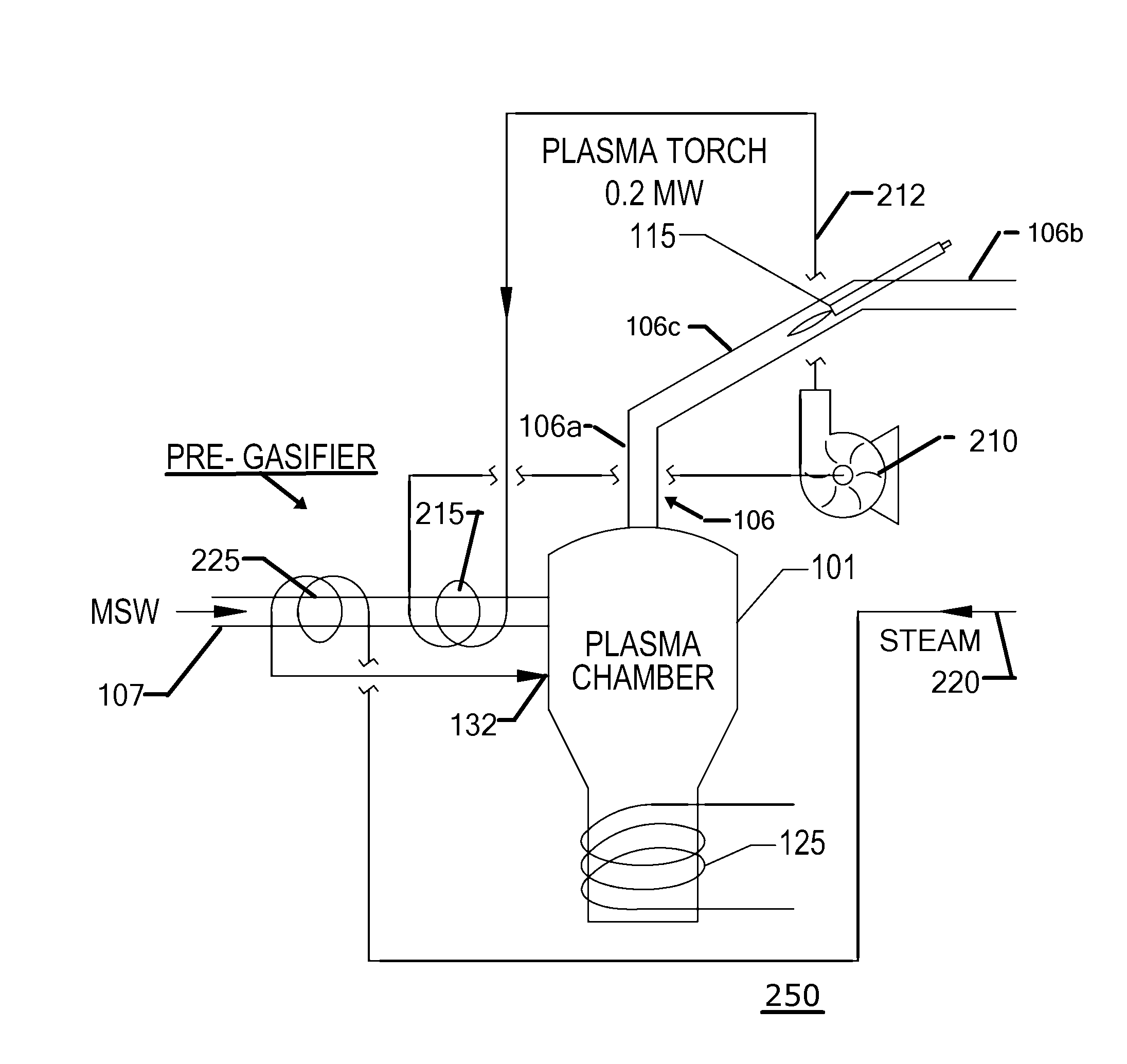
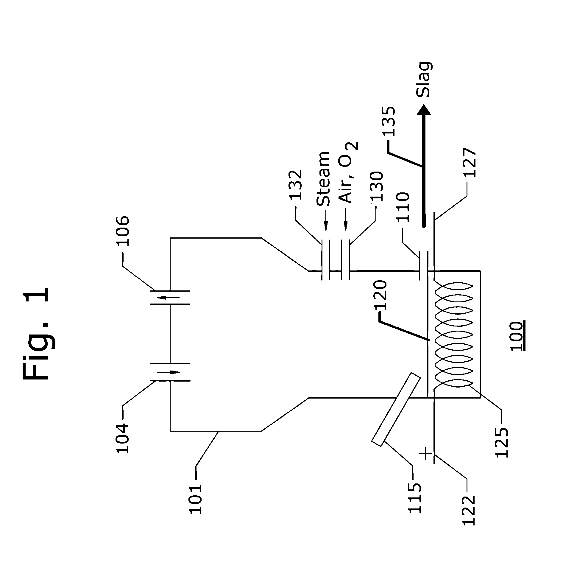
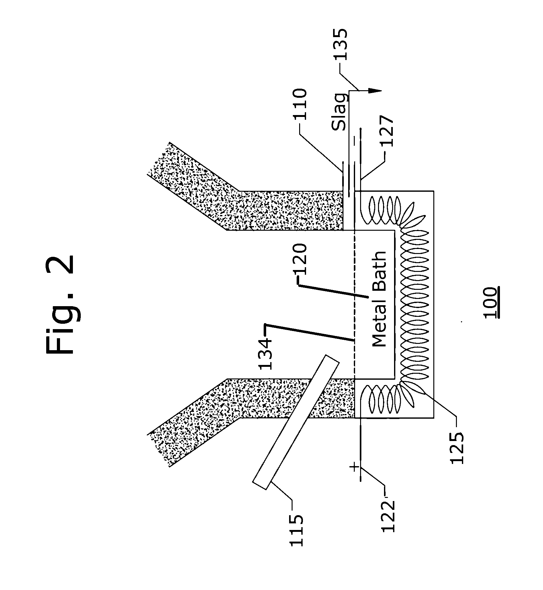
[0032]FIG. 1 is a simplified schematic representation of a cupola arrangement 100 constructed in accordance with the invention. As shown in this figure, a cupola shell 101 is provided with an inlet 104 for introducing a feedstock (not shown) that in some embodiments of the invention is a renewable feedstock, a fossil fuel, or a hazardous waste (not shown). Any combination of the three forms of feedstock can be used in the practice of the invention. There is additionally provided in an outlet port 106 for enabling removal of the generated syngas (not shown). In contrast to conventional inductive furnaces that facilitate a large outlet for metal or alloy production, there is no other outlet for such product. There is but an additional small drain 110 for eliminating inorganic slag.

[0033]It is a feature of the present invention that primarily organic compounds are processed to produce syngas. The specific illustrative embodiment of the invention described herein is essentially a bucket...


PUM

PropertyMeasurementUnit
Angleaaaaaaaaaa
Energyaaaaaaaaaa
Heataaaaaaaaaa

Abstract

A method of generating syngas as a primary product from renewable feedstock, fossil fuels, or hazardous waste with the use of a cupola. The cupola operates selectably on inductive heat alone, chemically assisted heat, or plasma assisted heat. Additionally, the operation of the cupola is augmented by the use of direct acting carbon or graphite rods that carry electrical current for additional heat generation into the metal bath that is influenced by the inductive element. The method includes the steps of providing a cupola for containing a metal bath; and operating an inductive element to react with the metal bath. Feedstock in the form of a combination of fossil fuel, a hazardous waste, and a hazardous material is supplied to the cupola. A plasma torch operates on the metal bath selectably directly and indirectly. Steam, air, oxygen enriched air, and oxygen are supplied in selectable combinations.

Description

BACKGROUND OF THE INVENTION[0001]1. Field of the Invention[0002]This invention relates generally to a new and novel design for a cupola to generate a syngas. One of the main applications for the cupola is in the field of renewable power generation. The cupola can operate on an inductive metal bath heating system only or it can be assisted by a plasma torch system.[0003]2. Description of the Related Art[0004]Inductive heating furnaces have existed for some time. They have been applied to the purpose of processing metals and ores. The furnaces have been optimized in many ways for this process including trunion tilting methods and special ore charging systems. The furnaces have proven to be robust in the metal processing industry.[0005]In an unrelated industry plasma has been utilized to process renewable feedstocks, fossil fuels, and hazardous materials for the purpose of producing syngas as a primary product. This process, which includes plasma gasification, continues to grow in popu...

Claims


Application Information

Patent Timeline
IPC IPC(8): C01B3/02
CPCC01B3/02F23G5/027F23G5/085F23G2202/20F23G2204/201F23G2204/204C01B3/342C01B3/348C01B2203/0216C01B2203/0255C01B2203/0861C21B13/0073Y02E20/12C10J3/57C10J2300/1238Y02E20/34Y02P10/32Y02P20/129Y02E20/18C10J2300/0946C10J2300/0956C10J2300/0959C10J2300/0976C10J2300/1276C10J2300/1675F01K7/16F01K13/006
Inventor JURANITCH, JAMES CHARLES
Owner PLASMA TECH HLDG LLC
Why Eureka
Try Eureka