Load driving apparatus and driving method thereof

Inactive Publication Date: 2014-06-19
BEYOND INNOVATION TECH
View PDF11 Cites 4 Cited by
  • Summary
  • Abstract
  • Description
  • Claims
  • Application Information

AI Technical Summary

Benefits of technology

The invention is a load driving apparatus that can control the dimming of LED lights. It uses a method called PWM (pulse width modulation) to adjust the brightness of the LEDs. The apparatus can adjust the duty cycle of the PWM signal to match different dimming needs, making sure that the LEDs have enough power during dark operations. This means that the LEDs can operate without stopping, and the apparatus doesn't need a larger capacitor to support it during this period. This reduces processing costs and also reduces the space required on the circuit board.

Problems solved by technology

Therefore, when LED(s) is / are in full dark state, the control chip in the LED driving apparatus may not operate normally due to insufficient power.
Nevertheless, the LED driving apparatus may still stop operating when said capacitor is insufficient.
In addition, if increasing the capacitance of the large external capacitor, not only the processing cost is increased, but also an area required for a printed circuit board (PCB) is increased.

Method used


Image

  • Load driving apparatus and driving method thereof
  • Load driving apparatus and driving method thereof
  • Load driving apparatus and driving method thereof

Examples


Embodiment Construction

[0027]Reference will now be made in detail to the present preferred embodiments of the invention, examples of which are illustrated in the accompanying drawings. Wherever possible, the same reference numbers are used in the drawings and the description to refer to the same or like parts.

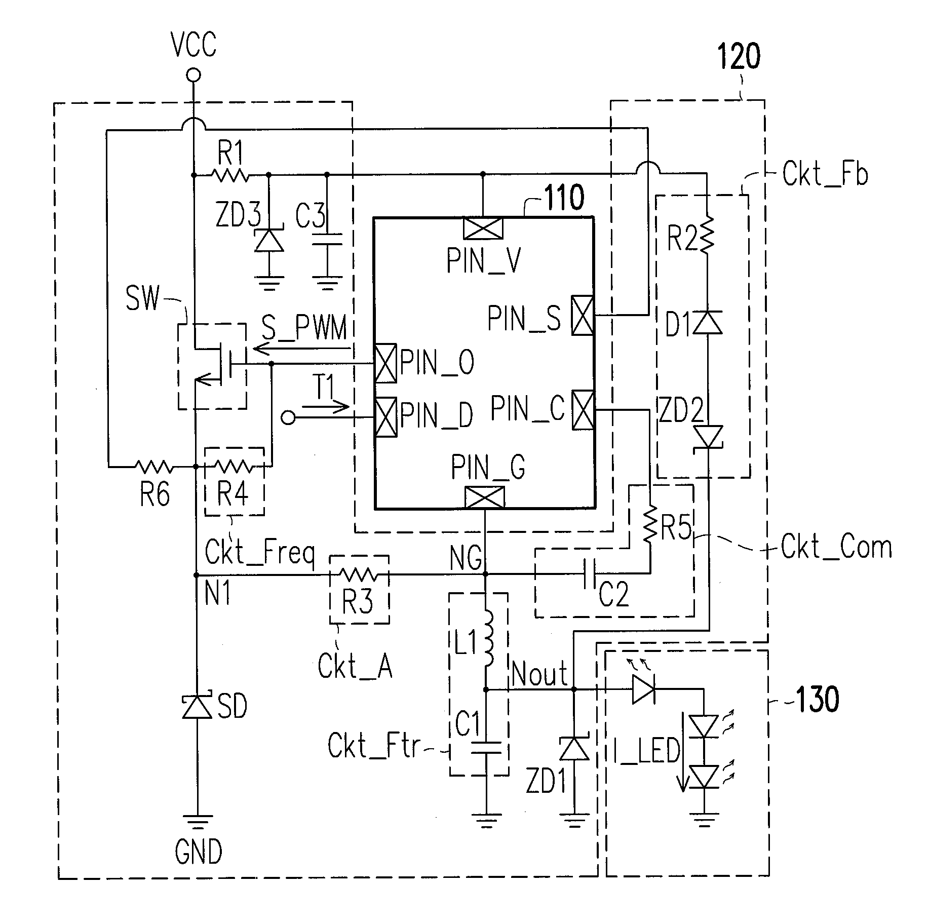
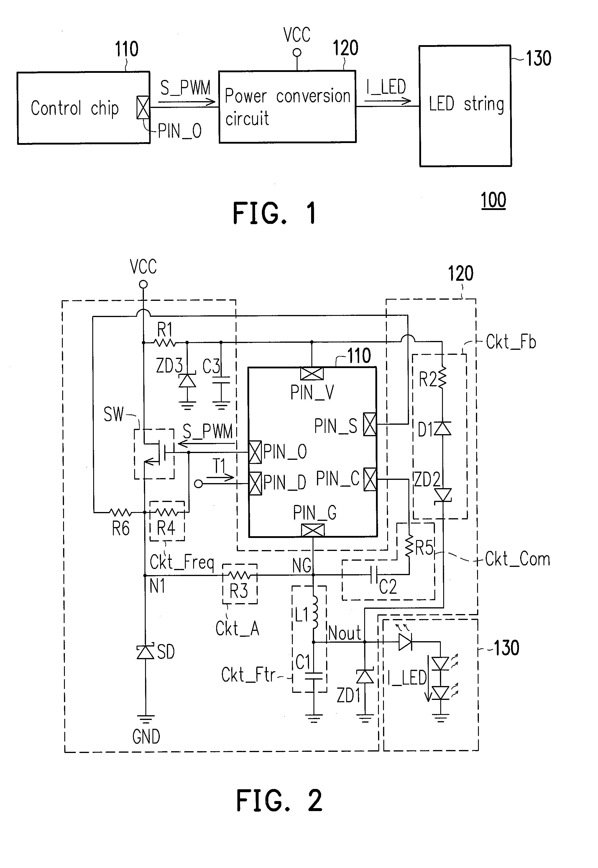
[0028]FIG. 1 is a block schematic view of a load driving apparatus according to an embodiment of the invention. In the present embodiment, a load driving apparatus 100 is at least suitable for driving a light-emitting diode (LED) load such as an LED string 130. Referring to FIG. 1, the load driving apparatus 100 includes a power conversion circuit 120 and a control chip 110. The power conversion circuit 120 is coupled to the LED string 130. The control chip 110 is coupled to the power conversion circuit 110 and configured to control the operation(s) of the power conversion circuit 120. In a structure / configuration of the power conversion circuit 120 as illustrated in FIG. 1, the power conversion circ...


PUM


Abstract

A load driving apparatus and a driving method thereof are provided. The load driving apparatus includes a power conversion circuit and a control chip. The power conversion circuit receives a DC input voltage, and drives an LED load in response to a gate PWM signal. The control chip is configured to: provide the gate PWM signal having a first preset duty cycle during a light operation period of a dimming operation, so that the LED load is fully turned on; and provide the gate PWM signal having a second preset duty cycle during a dark operation period of the dimming operation, so that the LED load is slightly turned on. The second preset duty cycle is far less than the first preset duty cycle. A current of the LED load during the light operation period is far more than a current of the LED load during the dark operation period.

Description

CROSS-REFERENCE TO RELATED APPLICATION[0001]This application claims the priority benefit of Taiwan application serial no. 101147621, filed on Dec. 14, 2012. The entirety of the above-mentioned patent application is hereby incorporated by reference herein and made a part of this specification.BACKGROUND OF THE INVENTION[0002]1. Field of the Invention[0003]The invention relates to a load driving apparatus, and particularly to, a light-emitting diode driving apparatus and a driving method thereof.[0004]2. Description of Related Art[0005]Conventionally, a light-emitting diode (LED) driving apparatus is generally composed by circuits such as a control chip, a power switch and an external circuit, etc. The control chip may provide a driving signal to switch the power switch, so that the LED(s) may emit light according to a current generated by switching of the power switch. In order to achieve a high contrast ratio with conventional LED dimming technologies, a Pulse Width Modulation (PWM)...

Claims


Application Information

Patent Timeline
IPC IPC(8): H05B33/08H05B44/00
CPCH05B45/375
Inventor LIN, CHIU-YUANHUANG, NAN-CHUANKAO, CHEN-LUNG
Owner BEYOND INNOVATION TECH
Why Eureka
Try Eureka