Implantable and removable customizable body conduit

a customizable, body technology, applied in the field of implants and customizable body conduits, can solve the problems of inability to direct anastomosis in all patients, discomfort, and increased risk of bleeding and infection in patients, and achieve the effects of preventing in vivo adhesion, minimal tissue and vasculature response, and improving the patency of a vascular segmen

Active Publication Date: 2014-06-26
MERIT MEDICAL SYST INC
View PDF13 Cites 4 Cited by
  • Summary
  • Abstract
  • Description
  • Claims
  • Application Information

AI Technical Summary

Benefits of technology

[0009]As used herein “remodeling” is a broad term and includes the durable widening of a previously narrowed body vessel to a larger size, permitting a greater degree of flow, less flow resistance, less back pressure, and / or other flow benefits. The embodiments described herein can find application in any body conduit, such as any blood vessel. Arterial and venous vessels can be treated with these apparatuses and methods. Also, a variety of such vessels of different size and body regions can be treated. This method can be applied anywhere in the vasculature, but is has been tested with great success in the venous vasculature. Other body lumens outside the vascular system can be treated as well, including the esophagus, respiratory and nasal passages, lumens of the gastro-intestinal track, urinary tract, biliary duct.

Problems solved by technology

Moreover, a direct anastomosis may not be feasible in all patients due to anatomical considerations.
However, AV grafts still require time for the graft material to mature prior to use, so that a temporary access device, such as a Quinton catheter, must be inserted into a patient for hemodialysis access until the AV graft has matured.
The use of temporary catheter access exposes the patient to additional risk of bleeding and infection, as well as discomfort.
Also, patency rates of ePTFE access grafts are still not satisfactory, as the overall graft failure rate remains high.
These failure rates are further increased in higher-risk patients, such as diabetics.
These access failures result in disruption in the routine dialysis schedule and create hospital costs of over $2 billion per year.
This is frequently a problem in dialysis patients due to placement of previous catheters for dialysis access, as described by Davis, D, Petersen, J, Feldman, R, et al.

Method used


Image

  • Implantable and removable customizable body conduit
  • Implantable and removable customizable body conduit
  • Implantable and removable customizable body conduit

Examples


embodiment 4

[0081]FIG. 8 shows a general trend to lower attachment forces for Embodiment 4 compared to other embodiments. Embodiment 4 had lower values for the height and the length of the barb 248. Also, FIG. 8 shows that a lower pic count of the braided structure of the catheter can result in a significantly lower attachment force compared to a higher pic count arrangement, where the connector has two barbs. Lowering the attachment force is desirable in some embodiments to provide faster and easier assembling of a vascular access system in-situ for the clinician.

embodiment 2

[0082]FIG. 7 shows that for the embodiments described in the table above, retention force (e.g., the force needed to disconnect the catheter 100 from the connector 200) was not highly dependent on pic count for the embodiments of the connector studied. Although there is an increase in retention force for Embodiment 2 compared to the other embodiments, all four embodiments had relatively high retention forces compared to an engagement mechanism including a connector with a single barb engaged with a catheter having a braided structure.

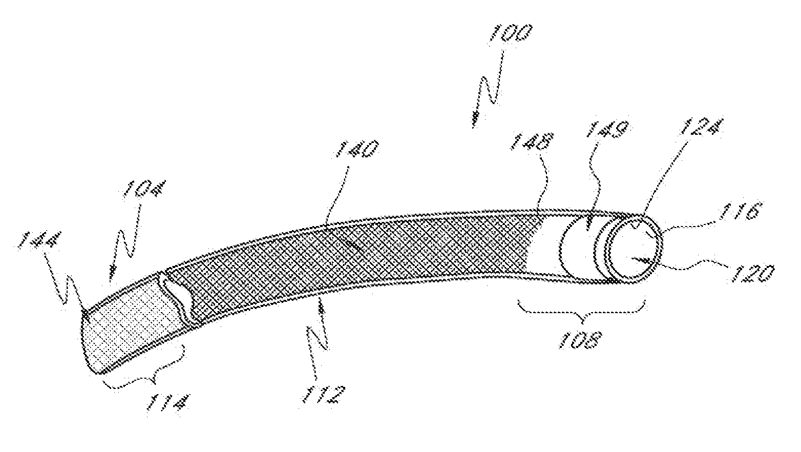
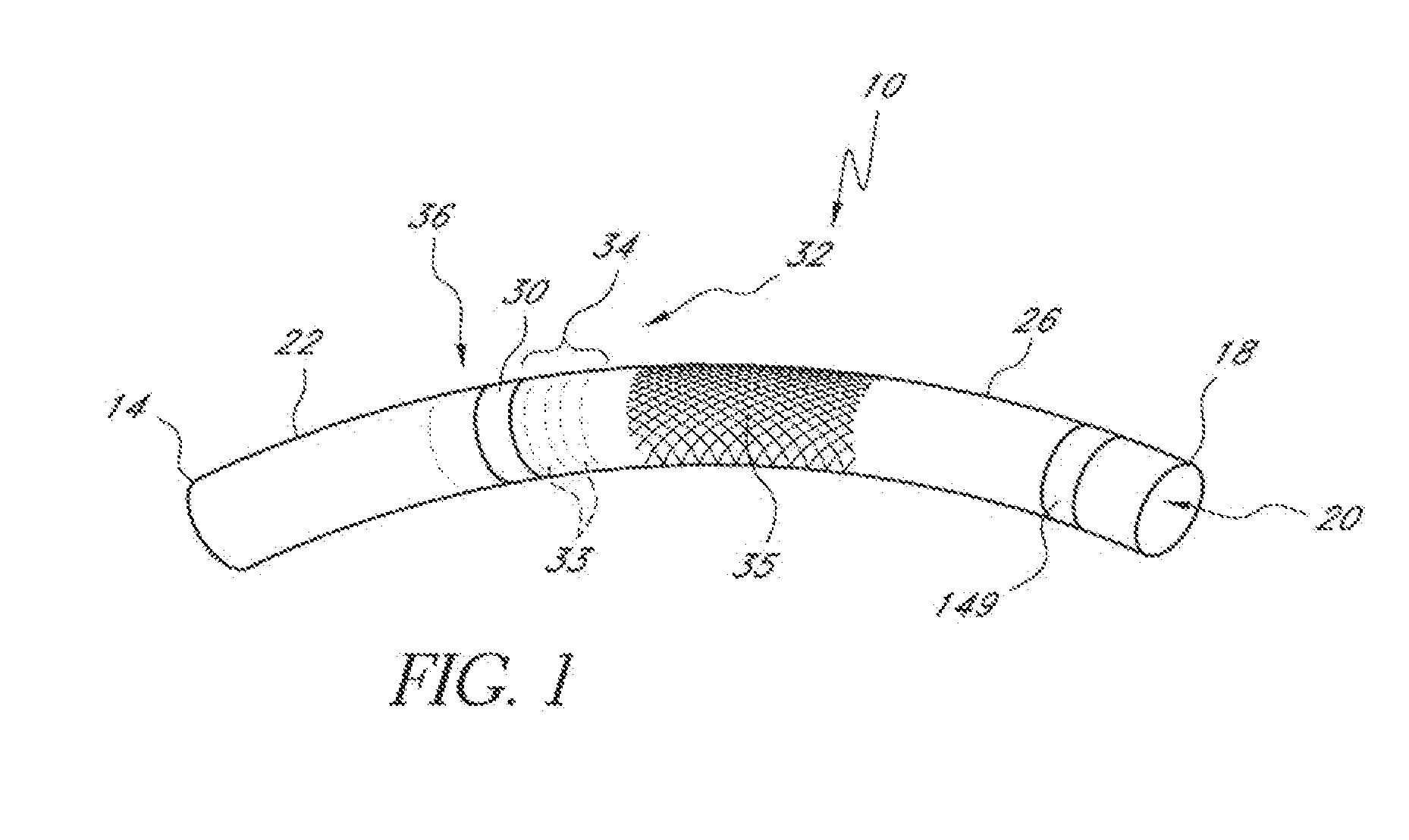
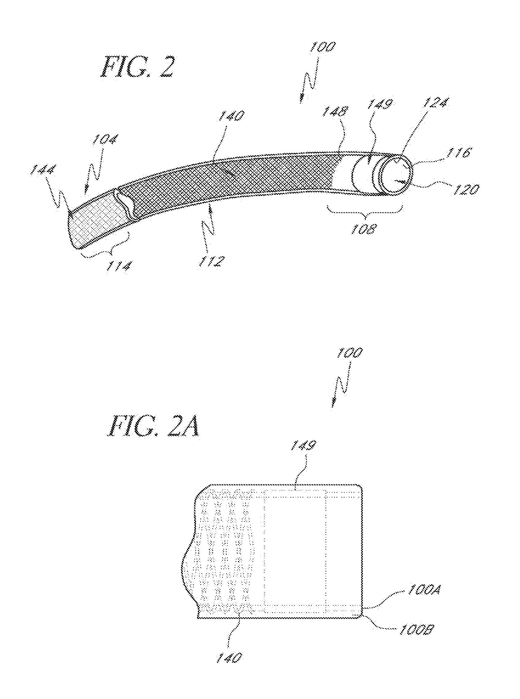
[0083]Also, the performance of the braided structure 140 can relate to the number of wires incorporated into the weave. In some embodiments, the braided structure 140 includes about forty-eight braided members 152. Other numbers of braided members 152 can be provided, however. For example, in one embodiment, twenty-four braided members 152 can be provided. Fewer wires provide less crush and kink resistance. More wires provide greater resistance in the b...


PUM


Abstract

An apparatus and method are provided to treat a stenosis. A delivery device is provided that has an elongate tubular member coupled therewith. The elongate tubular member has an outside surface that is configured to prevent adherence of in vivo matter. The tubular member has a proximal end and a distal end and is reinforced along its length to maintain open lumen under a transverse load. The tubular member is placed in the vasculature such that the distal end of the elongate tubular member is disposed distal of a stenosis. The proximal end of the elongate tubular member is disposed inside the vessel, preferably at a location proximal of the stenosis. Thereafter, after a therapeutic period, the elongate tubular member is removed intact.

Description

CROSS-REFERENCE TO RELATED APPLICATIONS[0001]This application is a divisional of U.S. application Ser. No. 13 / 151,157, filed Jun. 1, 2011, which is a continuation-in-part of U.S. application Ser. No. 12 / 397,275, filed Mar. 3, 2009, which claims priority to and the benefit of U.S. Provisional Application No. 61 / 034,125, filed Mar. 5, 2008, which are all hereby incorporated by reference herein in their entirety. Each of the following applications also is incorporated by reference herein in its entirety: U.S. application Ser. No. 11 / 600,589, filed Nov. 16, 2006; U.S. application Ser. No. 11 / 216,536 filed on Aug. 31, 2005; and U.S. application Ser. No. 10 / 962,200, filed on Oct. 8, 2004.BACKGROUND OF THE INVENTIONS[0002]1. Field of the Inventions[0003]This application relates to systems and methods for treating or bypassing stenosis in a body conduit, and connecting multiple portions of fluid carrying conduits.[0004]2. Description of the Related Art[0005]In the United States, approximate...

Claims


Application Information

Patent Timeline
Patent Type & Authority Applications(United States)
IPC IPC(8): A61M1/36
CPCA61F2/064A61M25/005A61M2025/0024A61F2250/0059A61M1/3655
Inventor DANN, MITCHELLHERRIG, JUDSON A.HOHMANN, STEPHEN
Owner MERIT MEDICAL SYST INC
Why Eureka
Try Eureka