Direct blow-molded container manufacturing method and package

Active Publication Date: 2014-07-03
MITSUBISHI GAS CHEM CO INC
View PDF0 Cites 5 Cited by
  • Summary
  • Abstract
  • Description
  • Claims
  • Application Information

AI Technical Summary

Benefits of technology

The present invention relates to a structure that includes a polyolefin (A) and a metaxylylene group-containing polyamide (C) dispersed in the polyolefin (A). The polyolefin (A) can be modified with various additives such as antioxidants, matting agents, heat-resistant stabilizers, weathering stabilizers, ultraviolet absorbers, nucleating agents, plasticizers, flame retarders, antistatic agents, color protectors, and lubricants without affecting the overall effect of the invention. The polyolefin (A) can be blended with other polyolefins or other polymers to improve its strength against falling and shock. The acid-modified polyolefin (B) used in the invention is a polyolefin graft-modified with an unsaturated carboxylic acid or the anhydride thereof, which helps maintain the structure by bonding the polyolefin (A) to the metaxylylene group-containing polyamide (C) dispersed in the polyolefin (A). The acid-modified polyolefin (B) can be used in various ratios to the polyolefin (A) to achieve desired properties. The metaxylylene group-containing polyamide (C) is a thermally stable material that can be used in various applications.

Problems solved by technology

However, those multilayer containers cannot be produced in manufacturing facilities for conventional single-layer containers.
Therefore, producing a multilayer container in manufacturing facilities for conventional single-layer containers increases economic burden.
This can cause environmental load.

Method used


Image

  • Direct blow-molded container manufacturing method and package
  • Direct blow-molded container manufacturing method and package
  • Direct blow-molded container manufacturing method and package

Examples


example 1

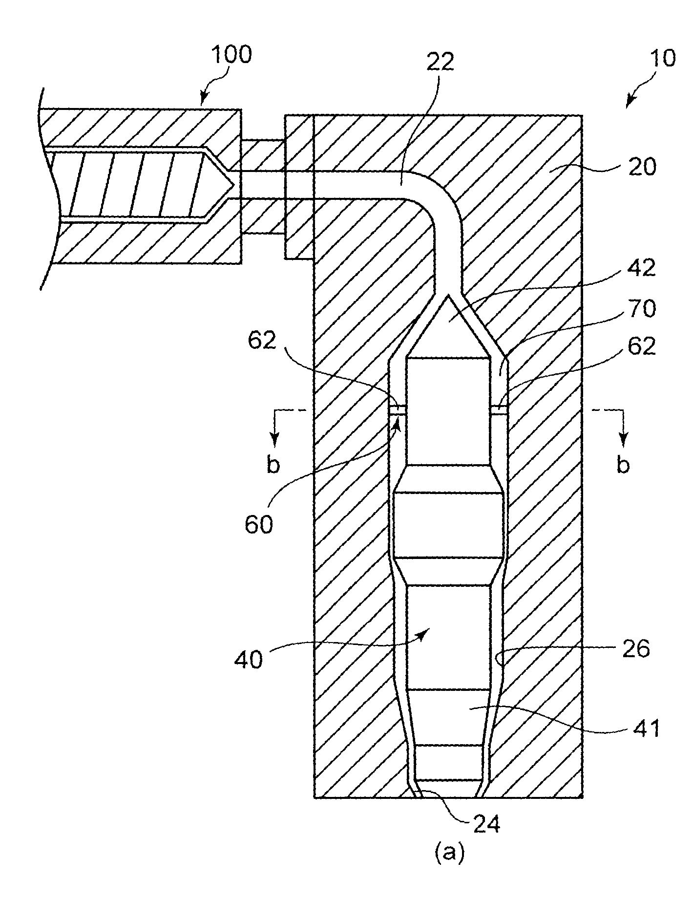
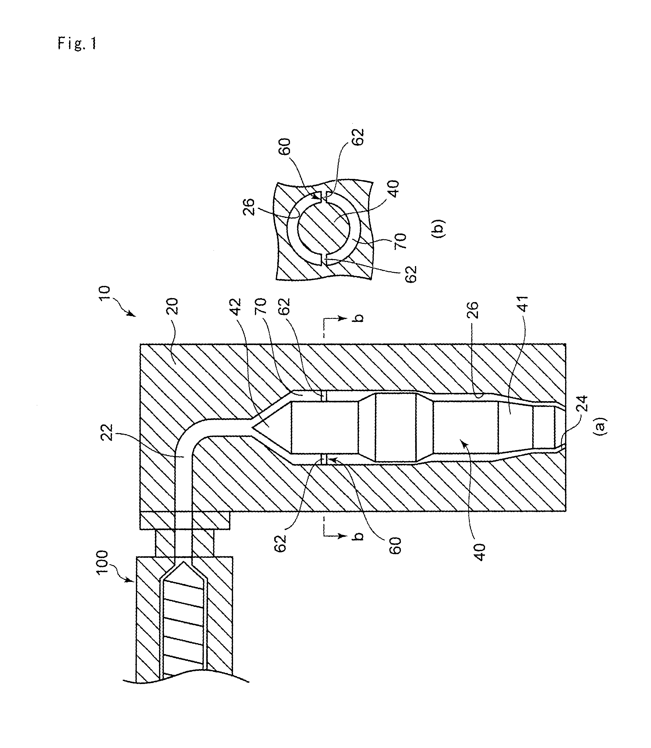
[0111]A device for forming a single-layer direct-blow molded container, which is equipped with a 55 mm single shaft extruder, a cylindrical die with the structure of FIG. 1, a mold, a mold clamping device, a cooler, and the like, was used. In the extrusion hopper, dry blend pellets of HDPE-1 / ADPE-1 / PA-1=85 / 10 / 5 (% by mass) were fed. The temperatures of the extruder cylinder, the adaptor, and the die were set to 210 to 235° C., 235° C., and 230° C., respectively. Subsequently, a parison was extruded at a screw rotation speed of 20 rpm. Then, a 400 mL columnar screw-capped bottle with a wall thickness of about 1 mm at the body was formed by direct blow molding.

example 2

[0112]Except for the mixing ratio rate of HDPE-1 / ADPE-1 / PA-1=80 / 10 / 10 (% by mass), a bottle was formed in the same manner as Example 1.

example 3

[0113]Except for the mixing ratio rate of HDPE-1 / LDPE-1 / ADPE-1 / PA-1=70 / 10 / 10 / 10 (% by mass), a bottle was formed in the same manner as Example 1.


PUM

PropertyMeasurementUnit
Percent by massaaaaaaaaaa

Abstract

The present invention provides a method of manufacturing a practical direct-blow molded container having excellent barrier property against fuels, chemicals, various gases including oxygen. The method of manufacturing a practical direct-blow molded container containing the metaxylylene group-containing polyamide (C) being dispersed and layered in the polyolefin (A) includes using a die provided with a die body having a flow hole in which the melted resin extruded from an extruder flows and a cylindrical hollow having an opening in the lower side and the flow hole in the upper side, the opening and the flow hole opening downward and upward, respectively, a mandrel having a tip in the upper side, the tip pointing to the opening of the tip of the flow hole, a flow path clearance formed between the hollow of the die body and the mandrel, the flow path clearance defining a resin flow path, and a support part formed in the flow path clearance, the support part holding the mandrel in the hollow of the die body.

Description

TECHNICAL FIELD[0001]The present invention relates to a method of manufacturing a container formed by direct blow molding and a package including the container.BACKGROUND ART[0002]Containers for preserving hydrocarbons, various chemicals, bathroom furnishings, sanitary products, cosmetics, beverages, and food pastes includes, for example, a fuel tank for cars or small engines, a bottle, a can, and a tube. In many cases, metal and glass conventionally used as the material are substituted with plastic. Plastic is characterized by saving the weight, eliminating rust prevention treatment, reducing breakability, and improving the degree of freedom of shape.[0003]Many of the containers for preserving various chemicals, bathroom furnishings, sanitary products, cosmetics, beverages, and food pastes are formed by polyolefins such as high density polyethylenes (hereinafter sometimes abbreviated as “HDPE”), linear low density polyethylenes (hereafter sometimes abbreviated as “LLDPE”), polyprop...

Claims


Application Information

Patent Timeline
IPC IPC(8): B65D1/00B29D22/00B29C48/09B29C48/32
CPCB29C47/20B29C47/0023B29D22/003B29C47/705B65D1/00B29C49/04B29K2077/00B29K2995/0067B29K2995/0069B29L2031/715B29L2031/7158B29L2031/7172B29C48/32B29C48/705B29C48/09B29C49/42B29K2023/00B29L2031/712
Inventor OTAKI, RYOJIKOUNO, KENJIKOBAYASHI
Owner MITSUBISHI GAS CHEM CO INC
Why Eureka
Try Eureka