Average current controller, average current control method and buck converter using the average current controller

a technology of average current and control method, which is applied in the direction of electric variable regulation, process and machine control, instruments, etc., can solve the problems of difficult control of average current, low efficiency, and change of the average current of the leds

Active Publication Date: 2014-07-03
SKAICHIPS CO LTD
View PDF6 Cites 19 Cited by
  • Summary
  • Abstract
  • Description
  • Claims
  • Application Information

AI Technical Summary

Benefits of technology

[0023]The present invention has been invented in order to overcome the above-described problems and it is, therefore, an object of the present invention to provide an average current controller, an average current control method and a buck converter using the average current controller capable of overcoming problems that the average current level is changed due to the delay generated in two comparator in the conventional average current controller and the control of current is difficult when the on-time is short.

Problems solved by technology

However, the PWM method capable of maximizing the efficiency is preferred to the linear control method having a low efficiency.
Accordingly, in case when the LED is controlled by using the buck converter using the off-time control method, there are problems as follows.
At first, since the load voltage drops of the LEDs have different characteristics for each manufacturer, it is difficult to control the average current.
Thirdly, since the whole load voltage is changed in case when the number of loads is changed, the average current of the LEDs are changed.
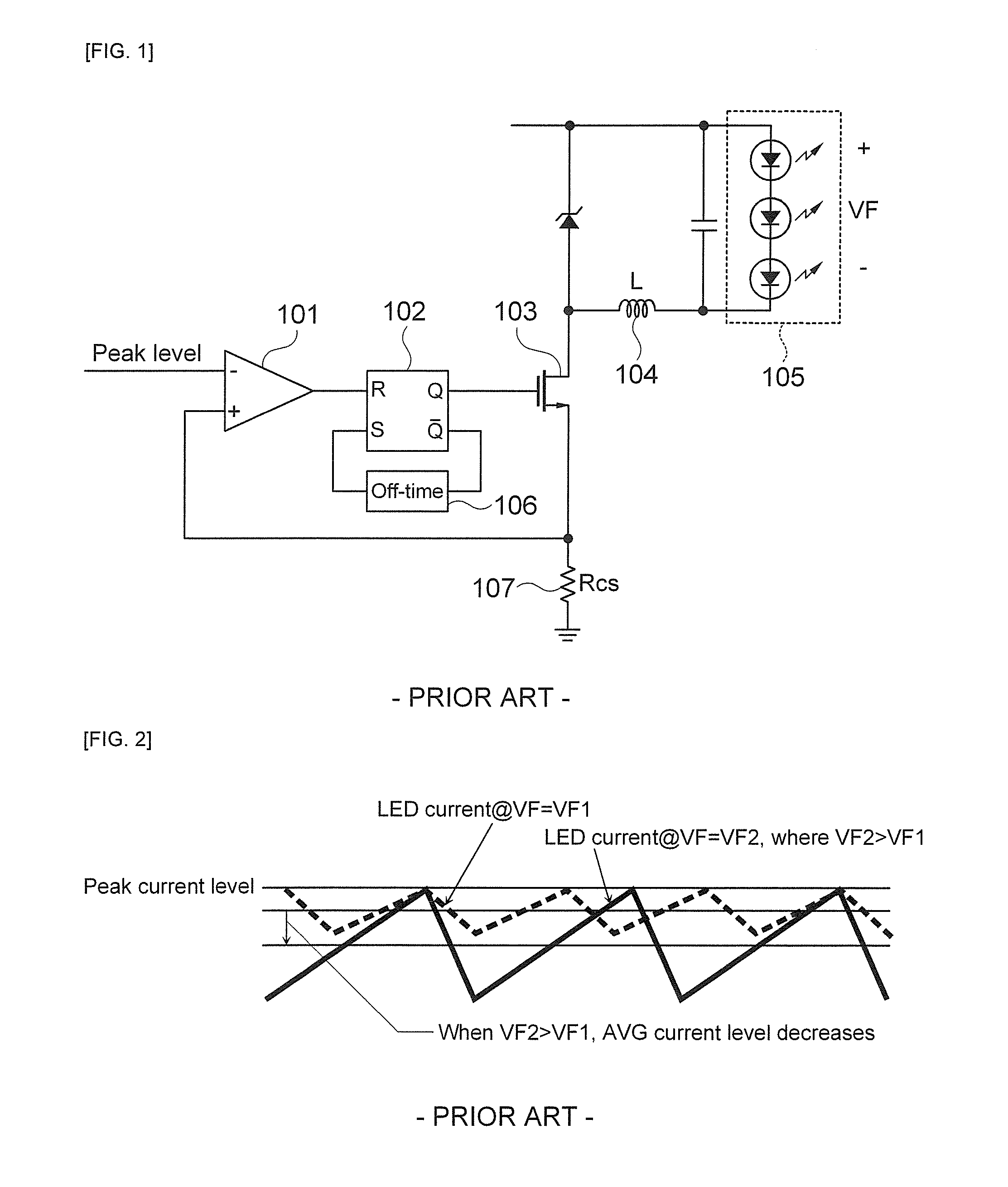
However, in the control method of the above conventional average current controller, two comparators are required for sensing to reach the average current IAVG and the peak current IPEAK, there is a problem that the average current level is changed due to the delay generated from a signal processing relationship of two comparators.
And also, in case when the on-time T1+T2 are very short, the control of the current becomes very difficult.

Method used


Image

  • Average current controller, average current control method and buck converter using the average current controller
  • Average current controller, average current control method and buck converter using the average current controller
  • Average current controller, average current control method and buck converter using the average current controller

Examples


Embodiment Construction

[0085]The terms or words used in the present specification and claims should not be interpreted as being limited to typical or dictionary meanings, but should be interpreted as having meanings and concepts relevant to the technical spirit of the present invention based on the rule according to which an inventor can appropriately define the concept of the term to describe his / her own invention in the best manner.

[0086]Throughout the specification, when an element is referred to as “including” another element, it can further include the other element rather than exclude the other element unless the context clearly indicates otherwise. Further, the terms “unit”, “module”, “apparatus”, etc. used in the present specification represent a unit for processing at least one function or operation and may be implemented by hardware, software, or a combination thereof.

[0087]Hereinafter, embodiments of the present invention will be described in detail with reference to the accompanying drawings.

[...


PUM


Abstract

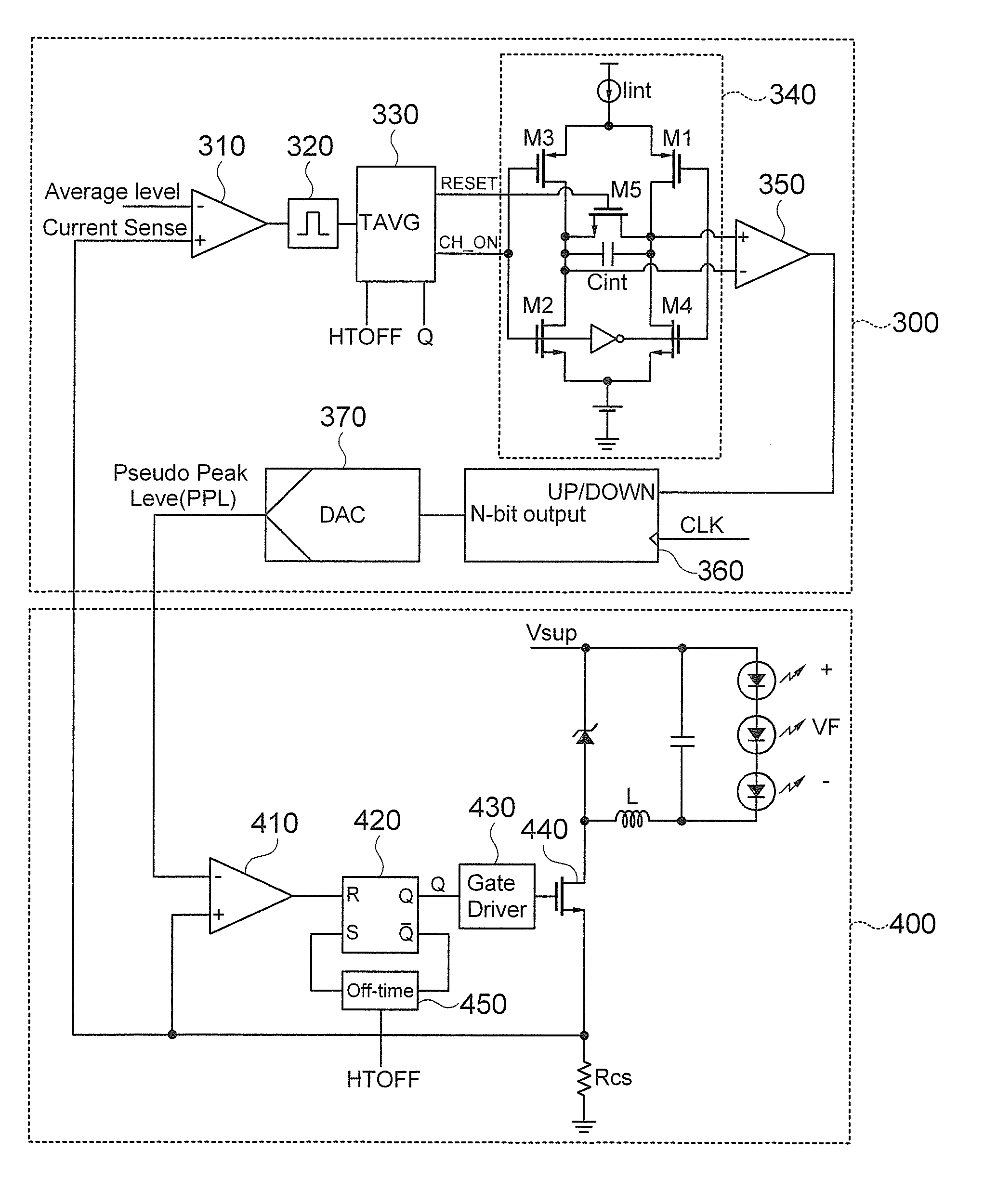
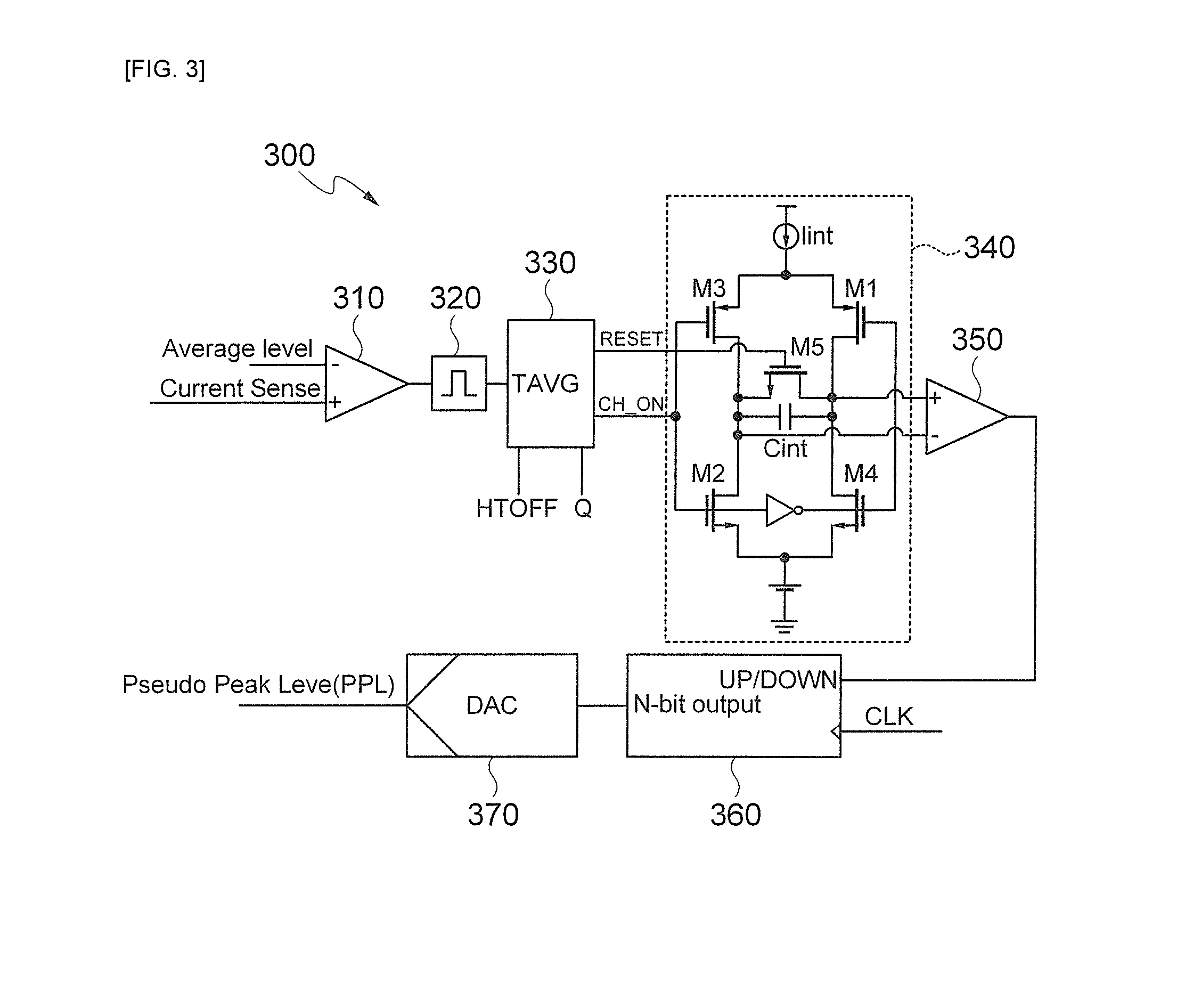
The present invention relates to an average current controller, an average current control method and a buck converter using the average current controller. The average current controller includes a first comparator for generating a high H signal, a multivibrator for generating a TAVG pulse signal by receiving a high H signal outputted from the first comparator, a timing generator for generating a signal CH_ON to charge/discharge a capacitor by using at least the TAVG pulse signal, an integrator circuit unit for charging/discharging the capacitor, a second comparator for outputting a corresponding signal, an up/down counter for increasing or decreasing a counting value and a digital/analog converter for outputting by converting an output (digital signal) of the up/down counter into an analog signal.

Description

CROSS-REFERENCE TO RELATED APPLICATIONS[0001]Claim and incorporate by reference domestic priority application and foreign priority application as follows:“CROSS REFERENCE TO RELATED APPLICATION[0002]This application claims the benefit under 35 U.S.C. Section 119 of Korean Patent Application Serial No. 10-2012-0155035, entitled filed Dec. 27, 2012, which is hereby incorporated by reference in its entirety into this application.”BACKGROUND OF THE INVENTION[0003]1. Field of the Invention[0004]The present invention relates to an average current controller, an average current control method and a buck converter using the average current controller; and more particularly, to an average current controller, an average current control method and a buck converter using the average current controller capable of overcoming problems that an average current level is changed and a current control becomes difficult in case when an on-time is short.[0005]2. Description of the Related Art[0006]In gen...

Claims


Application Information

Patent Timeline
Patent Type & Authority Applications(United States)
IPC IPC(8): H02M3/157H05B44/00
CPCH02M3/157Y02B20/30H05B45/375H02M3/155
Inventor HWANG, JONG TAEPARK, CHAN WOOCHA, SANG HYUNPARK, DEUK HEELEE, YUN JOONG
Owner SKAICHIPS CO LTD
Why Eureka
Try Eureka