Apparatus and control method therefor

a technology of apparatus and control method, applied in the field of imaging apparatus, can solve the problems of image quality decline and increase in significance, and achieve the effects of reducing processing time, increasing throughput, and reducing the time required to image the object and generate the digital imag

Inactive Publication Date: 2014-07-03
CANON KK
View PDF7 Cites 7 Cited by
  • Summary
  • Abstract
  • Description
  • Claims
  • Application Information

AI Technical Summary

Benefits of technology

[0005]In an imaging apparatus that generates high-resolution and wide-range digital images, the time required to image the object and generate the digital image should be reduced. In particular, in an imaging apparatus that is used for diagnostics or analysis, as in the case of a digital microscope, the image processing of large-volume objects (slides or the like) is sometimes performed in a batch mode, and it is highly desirable that the processing time be reduced and the throughput be increased. Accordingly, in order to increase the speed of imaging and image generation, the inventor tried to reduce the number of imaging cy

Problems solved by technology

However, a problem arising when the field of view of the optical system and the image pickup area of the image sensor are enlarged is that image quality decreases (blurring of the image), as described hereinbelow.
This

Method used


Image

  • Apparatus and control method therefor
  • Apparatus and control method therefor
  • Apparatus and control method therefor

Examples


first embodiment

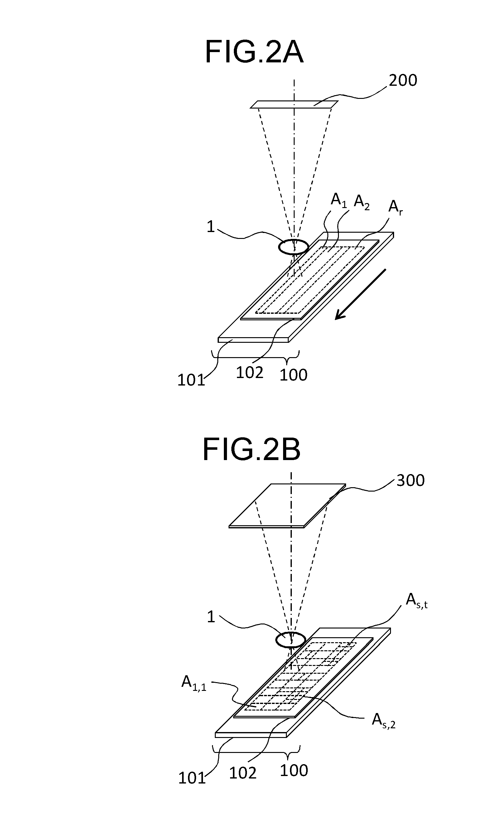
[0082]In the first embodiment of the present invention an example is explained in which the present invention is applied to an imaging apparatus using a line sensor as an image sensor. In the configuration of the entire system, one line sensor is disposed with respect to one imaging optical system 1, as shown in FIG. 2A.

[0083](Configuration of Imaging Apparatus)

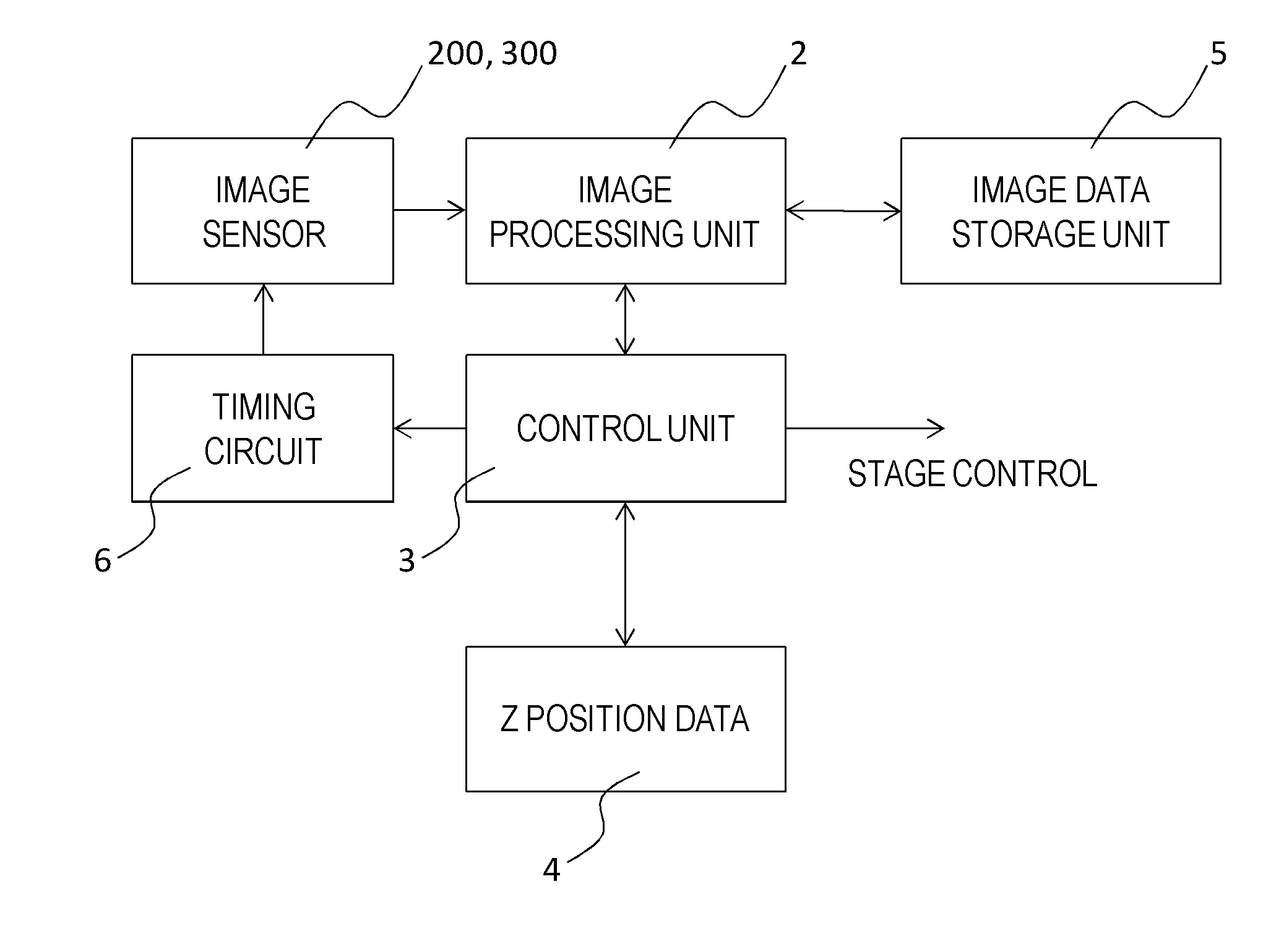
[0084]FIG. 3 is a block diagram illustrating the imaging apparatus of the first embodiment of the present invention. The imaging apparatus has a line sensor 200, which is an image sensor, an image processing unit 2, a controller unit 3, a memory 4 that stores data on the Z positions of the substances, an image data storage unit 5 that stores the created image data, and a timing circuit 6 that generates the operation timing of the line sensor 200. The imaging apparatus also has a stage that supports the slide, an illumination system that illuminates the slide, an imaging optical system that enlarges the optical image of the su...

second embodiment

[0117]The second embodiment of the present invention is described below. In the above-described first embodiment, the regional Z-positions spread is calculated from the results obtained by performing actual measurements on the slide, whereas in the second embodiment, the regional Z-positions spread is determined from the statistical data acquired from a database.

[0118]The configuration of the second embodiment is identical to that of the first embodiment, as shown in FIG. 3. The main difference between the second embodiment and the first embodiment is in the processing procedure. FIG. 8 illustrates a specific operation of the controller unit 3 and the image processing unit 2 of the second embodiment of the present invention. The operation steps shown in FIG. 8 are explained successively below.

[0119]First, in step ST201, information on the spread of the Z positions of the substances is read from the database. The database may be provided in the memory 4 of the imaging apparatus, or m...

third embodiment

[0128]The third embodiment of the present invention is explained below. In the third embodiment of the present invention, the imaging regions are determined by an algorithm that is simpler than those used to determine the imaging regions from the regional Z-positions spread in the first and second embodiments.

[0129]The configuration of the imaging apparatus of the third embodiment which is shown in FIG. 3 is identical to that of the first and second embodiments. The main difference between the third embodiment and the first and second embodiments is in the processing procedure.

[0130]The processing flowchart of the third embodiment of the present invention is shown in FIG. 10.

[0131]Each operation step of the processing flow shown in FIG. 10 is explained below. First, in step ST301, the Z positions of the substances in the target slide are measured in the same manner as in step ST101 of the first embodiment. In this step ST301, the Z positions of the substances in the X, Y coordinates...


PUM


Abstract

An imaging apparatus controls a size of an imaging region according to a spread of Z positions of substances in an object. For example, the imaging region becomes wide when the spread is small and becomes narrow when the spread is large. Or, the number of image sensors to be used is increased when the spread is small and is decreased when the spread is large. Or, an image sensor having a wide image pickup area is used when the spread is small, and an image sensor having a narrow image pickup area is used when the spread is large.

Description

TECHNICAL FIELD[0001]The present invention relates to an imaging apparatus that images an object and generates a digital image.BACKGROUND ART[0002]An imaging apparatus that picks up images of a segmented object and generates a combined image of the entire object by merging together a plurality of the obtained partial images is known. For example, Patent Literature (PTL) 1 discloses an image reading device of a system such that the central portion of an image pickup range is focused on an object and the object images are successively picked up, while changing the camera angle. The problem associated with such a system is that when the optical axis of the camera is tilted with respect to the planar object, the end portions of the image pickup range are out of focus and the image is blurred. Accordingly, the image reading device described in PTL 1 uses the configuration in which the difference in distance from the camera at both ends of the image pickup range to the object plane is det...

Claims


Application Information

Patent Timeline
IPC IPC(8): G02B21/36
CPCG02B7/28G02B7/36G02B21/36G02B21/367G03B15/00G06T3/4038G02B21/361H04N5/23212G02B21/244H04N23/959
Inventor ABE, NAOTO
Owner CANON KK
Why Eureka
Try Eureka