Dual-Motor Drilling Machine with Controlled Feed Speed

a technology of controllable feed speed and drilling machine, which is applied in the direction of portable power-driven drilling machines, manufacturing tools, and portable drilling machines, etc., can solve the problems of poor surface condition of the hole or a deformation of the structure to be drilled, work hardening and heating during drilling operation, and deterioration of the drilling machine, so as to improve the compactness of the drilling machine

Active Publication Date: 2014-07-10
SETI TEC
View PDF56 Cites 6 Cited by
  • Summary
  • Abstract
  • Description
  • Claims
  • Application Information

AI Technical Summary

Benefits of technology

[0045]This implementation helps improve

Problems solved by technology

Indeed, an excessive feed speed can lead to poor surface condition of the hole or a deformation of the structure to be drilled.
However, an excessively high low speed can cause the drill to work at a level below that of the minimum chip thickness and cause work hardening and heating during the drilling operation.
Since controlled feed speed drilling machines can be used for drilling operations on costly elements such as for example aircraft structures, their deterioration as a result of poor contr

Method used


Image

  • Dual-Motor Drilling Machine with Controlled Feed Speed
  • Dual-Motor Drilling Machine with Controlled Feed Speed
  • Dual-Motor Drilling Machine with Controlled Feed Speed

Examples


Embodiment Construction

General Principle of the Invention

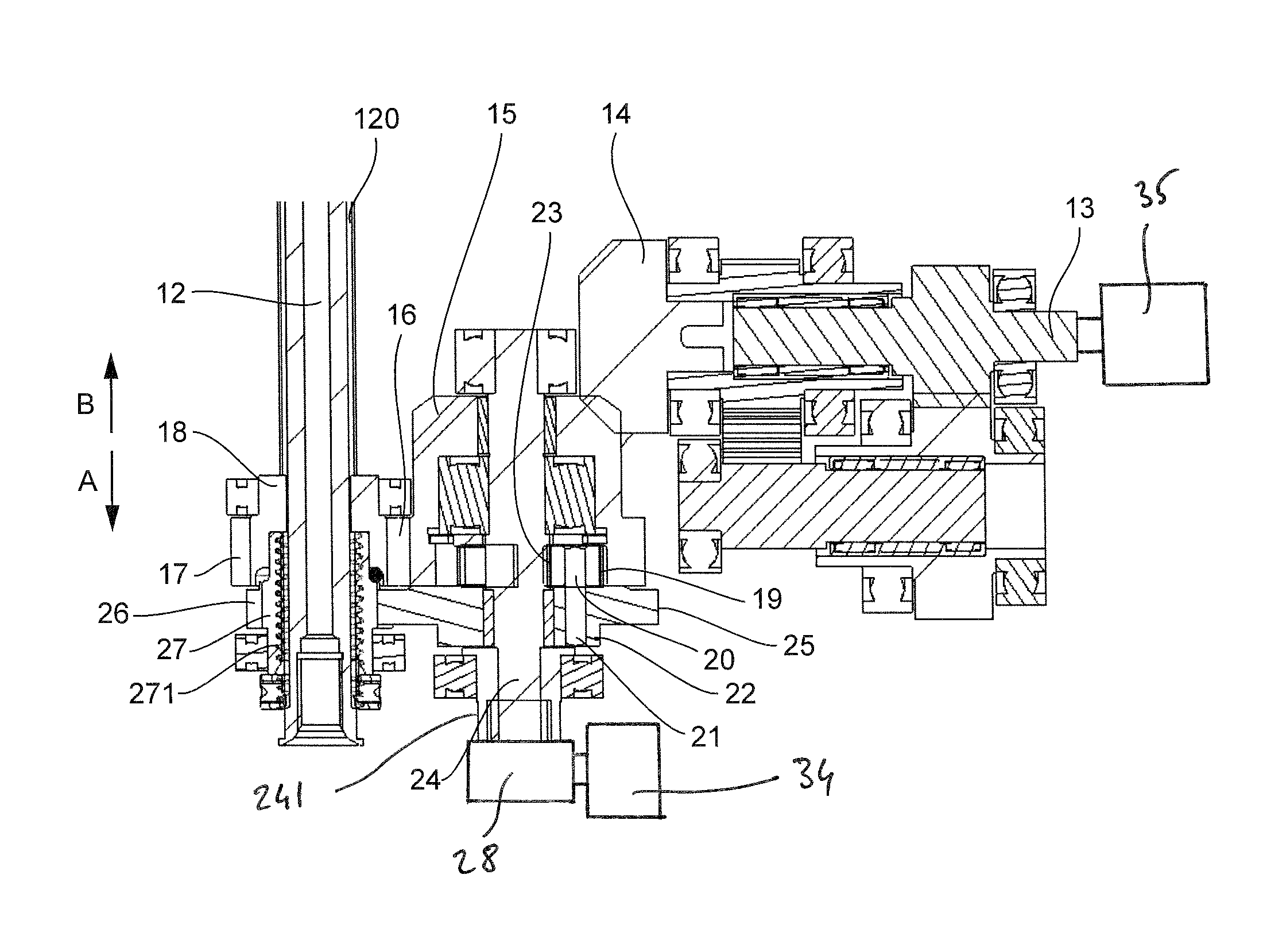
[0050]The general principle of the invention relies on the implementation in a drilling machine with controlled feed speed, comprising a rotationally driving motor for rotationally driving the output shaft and a feed motor enabling the driving in translation of this shaft, means for transmission planned so that the translation speed of the output shaft depends solely on the frequency of rotation of the feed motor and is completely independent of the frequency of rotation of the motor for rotationally driving the output shaft.

[0051]The reliability with which the feed speed of the output shaft is managed is therefore improved by the implementation of the invention which therefore plays a part in reducing the risks (deterioration of the machined pieces and / or of the cutting tools) related to poor management of the feed.

Example of an Embodiment of a Drilling Machine According to the Invention
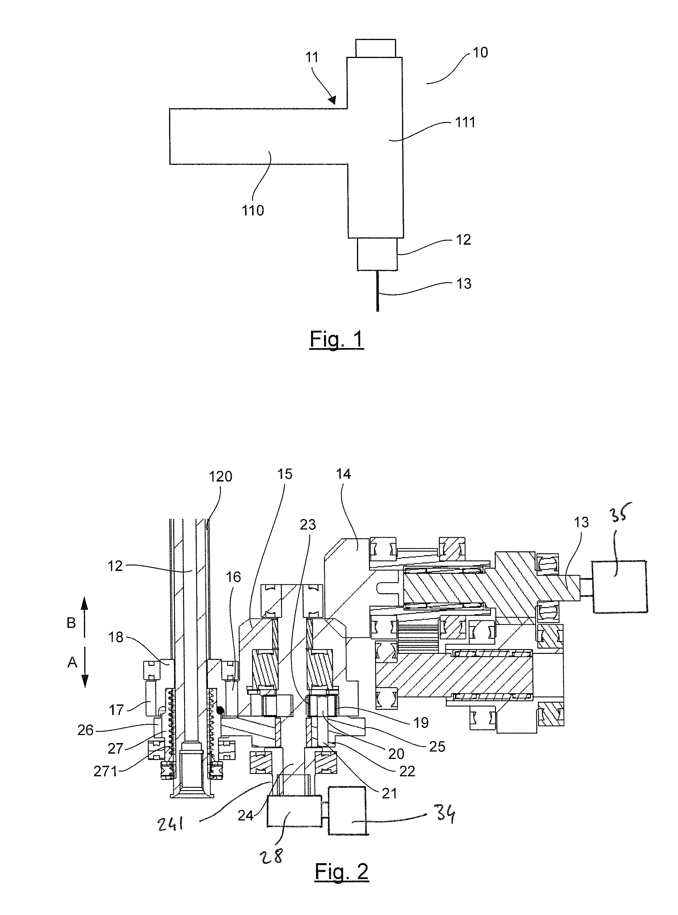
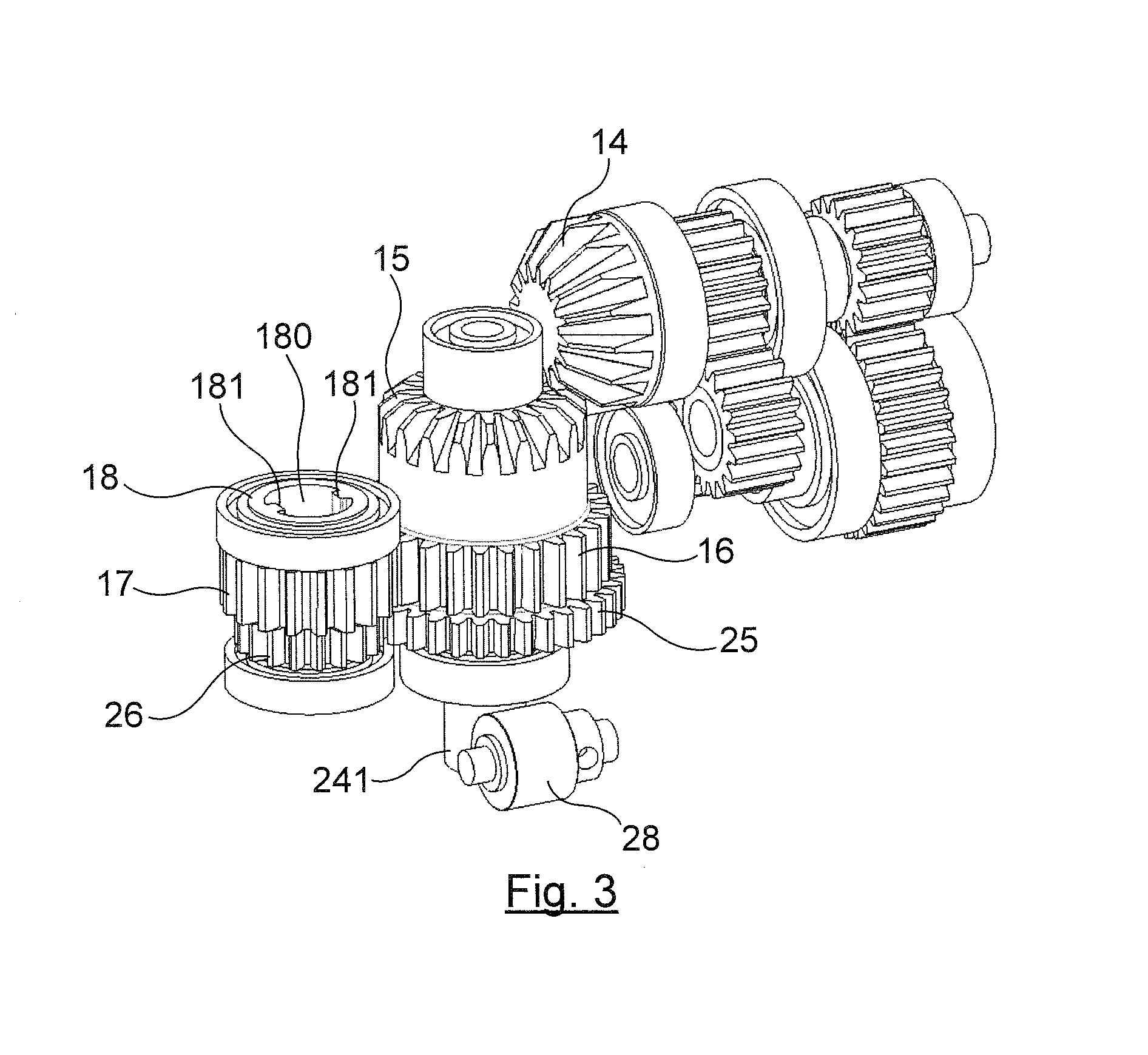
[0052]Architecture

[0053]Referring now to FIGS. 1 to 3, we pres...


PUM

PropertyMeasurementUnit
Speedaaaaaaaaaa
Frequencyaaaaaaaaaa

Abstract

A controlled feed speed drilling machine includes an output shaft for driving a cutting tool in motion. The output shaft is connected to first and second motors by a transmission, which includes a rotationally driving ring and a tapped drive nut. The driving ring is rotatable along the longitudinal axis of the output shaft via the transmission and the first motor. The output shaft is rotationally linked to the driving ring and is mobile in translation relative to the driving ring along the longitudinal axis via the transmission and the second motor. The tapped drive nut rotates along the longitudinal axis relative to the output shaft via the transmission and the first motor. The translation speed VT of the output shaft along its longitudinal axis is equal to the product of the rotation frequency FR of the second motor and a constant k according to VT=k. FR.

Description

FIELD OF THE INVENTION [0001]The field of the invention is that of the designing and manufacture of drilling tools more commonly called drilling machines.[0002]More specifically, the invention pertains to a drilling tool or drilling machine with a controlled feed speed.PRIOR ART[0003]There are known drilling machines whose output shaft, which is intended for driving a cutting tool such as a drill in motion, can be driven simultaneously in rotation and in translation along a same axis in order to carry out a drilling operation.[0004]The patent application FR-A1-2 881 366 describes a drilling machine of this kind. This drilling machine has a single motor connected to the output shaft by a transmission intended for driving the output shaft in translation and in rotation along a same axis. The automatic feed mechanism described in this document does not enable the management of both the rotation frequency and the feed speed of the drill in a drilling action because only one motor is use...

Claims


Application Information

Patent Timeline
IPC IPC(8): B23B39/10
CPCB23B39/10B23Q5/326Y10T408/675Y10T408/73Y10T408/65Y10T408/66B23B2260/07B25F5/001
Inventor PEREIRA, SEBASTIEN
Owner SETI TEC
Why Eureka
Try Eureka